Motor control device

Active Publication Date: 2009-10-15
DENSO CORP
View PDF21 Cites 12 Cited by
  • Summary
  • Abstract
  • Description
  • Claims
  • Application Information

AI Technical Summary

Benefits of technology

[0008]It is an object of the present invention to provide a motor control device capable of expanding the range of an available output voltage or an available output current by responding accurately to each response characteristic of switching elements.
[0010]One of the important features of the present invention is to adjust the dead time of the switching elements in each pair for each phase of the motor. For example, the control means adjusts the dead time for the pair of switching elements connected in series for each of U, V, and W phase of an three-phase AC motor. This control can use adopt a response characteristics of each switching elements such as MOSFETs, and can expand the output voltage range or the output current range of the motor.
[0011]The configuration of the motor control device according to the present invention allows the control means such as a microcomputer to independently set the dead time of the pair of switching elements for each phase of the motor. This allows the control means to independently adjust an optimum dead time of the pair of switching elements while considering the response characteristics of each switching element for each phase. It is thereby possible to expand the output range of the available output or the available current of the motor while taking full advantage of the response characteristics of each switching elements for each phase of the motor

Problems solved by technology

Thus, the conventional motor control devices do not cope with, namely, do not adopt each response characteristics of the MOSFETs, and thereby makes it difficult to expand the output voltage range or the output current range of the motor.

Method used


Image

  • Motor control device
  • Motor control device
  • Motor control device

Examples


first embodiment

[0025]A description will be given of the motor control device 1 according to the first embodiment of the present invention with reference to FIG. 1 to FIG. 7.

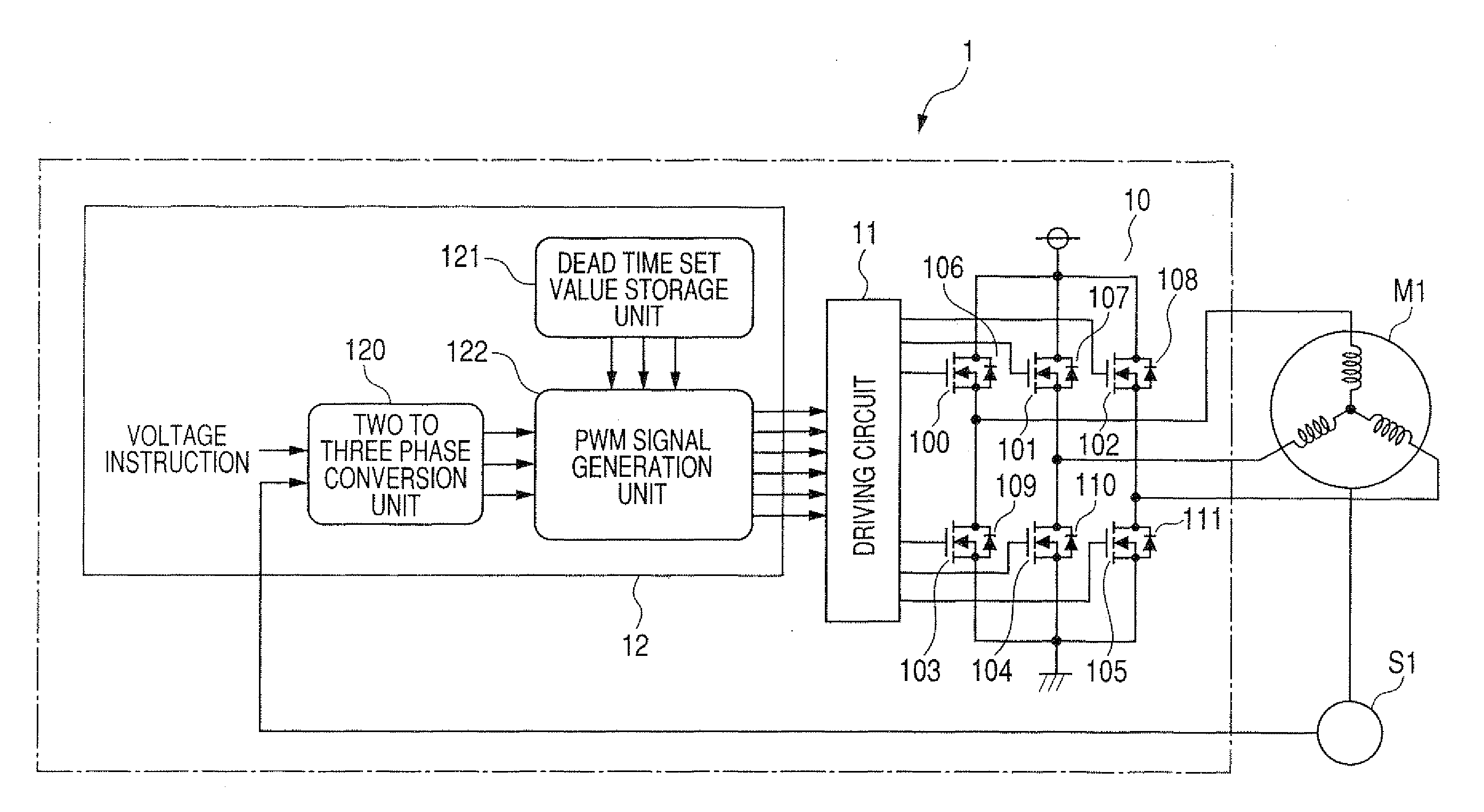
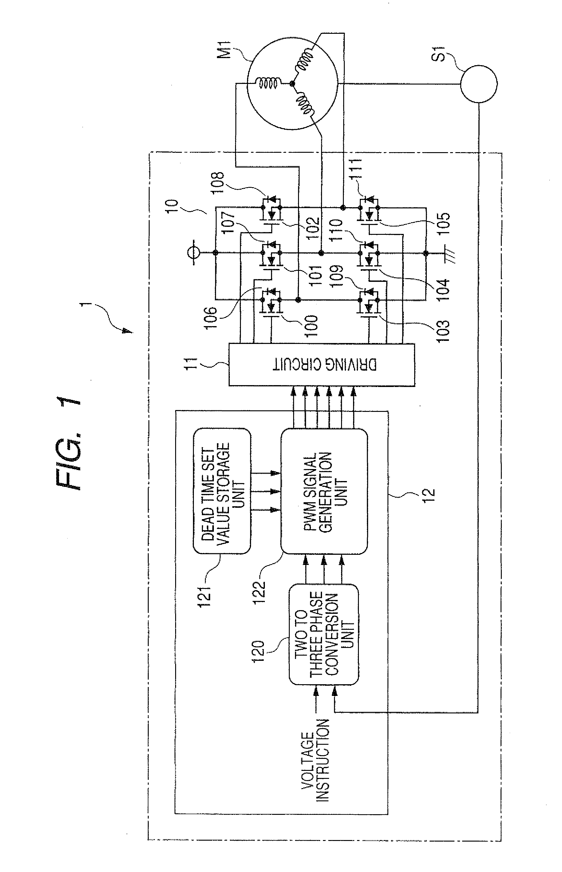
[0026]FIG. 1 is a block diagram showing the motor control device 1 according to the first embodiment.

[0027]The motor control device 1 shown in FIG. 1 is a device to control a three phase AC motor M1. The motor control device 1 controls a phase voltage to be supplied to the three phase AC motor M1. The three phase AC motor M1 is equipped with a rotation angle sensor S1.

[0028]The three phase AC motor M1 is composed mainly of the three phase bridge circuit 10 (as a multi-phase bridge circuit), a driving circuit 11, and a microcomputer 12 (as a control means).

[0029]The three phase bridge circuit 10 is composed of six MOSFETs 100 to 105 (as three pairs of switching elements). The microcomputer 12 instructs the driving circuit 11 to turn the MOSFETs 100 to 105 on and off.

[0030]As shown in FIG. 1, each of fly wheel diodes 106 to 111 i...

second embodiment

[0082]A description will be given of the motor control device according to the second embodiment of the present invention with reference to FIG. 9.

[0083]FIG. 9 is a block diagram showing the circuit structure of the motor control device 2 according to the second embodiment of the present invention. As shown in FIG. 9, the motor control device 2 is equipped with a microcomputer 22 (as a control means), a driving circuit 21, and a three phase bridge circuit 20 (as the multi-phase bridge circuit). The motor control device 2 controls the operation of a three phase AC motor M2 equipped with a rotation angle sensor S2. The microcomputer 22 is composed mainly of a three-phase conversion unit 290, a dead time set value storage unit 223, a PWM signal generation unit 224, an offset compensation value storage unit 221, and a dead time set value storage unit 223.

[0084]The three phase AC motor M2, the rotation angle sensor S2, the three phase bridge circuit 20, and the driving circuit 21 in the ...

third embodiment

[0094]A description will be given of the motor control device according to the third embodiment of the present invention with reference to FIG. 10.

[0095]FIG. 10 is a block diagram showing the circuit structure of the motor control device 3 according to the third embodiment of the present invention. As shown in FIG. 10, the motor control device 3 according to the third embodiment is equipped with a microcomputer 32 (as a control means), a driving circuit 31, and a three phase bridge circuit 30 (as the multi-phase bridge circuit). The motor control device 3 controls the operation of a three phase AC motor MS equipped with a rotation angle sensor S3.

[0096]The three phase AC motor M3, the rotation angle sensor S3, the three phase bridge circuit 30, and the driving circuit 31 in the third embodiment shown in FIG. 10 are the same in structure, function and operation of the three phase AC motor M1, the rotation angle sensor S1, the three phase bridge circuit 10, and the driving circuit 11 ...


PUM


Abstract

A motor control device has a three-phase bridge circuit, a driving circuit, and a microcomputer. The three-phase bridge circuit has three pairs of MOSFETs for U, V, and W phases of a three-phase AC motor as a control target. The microcomputer has a dead time set value storage unit and a PWM signal generation unit. The PWM signal generation unit generates a PWM signal with a dead time including a response characteristics of the pair of MOSFETs for each of U, V, and W phases of the AC motor based on a three-phase voltage instruction value supplied from an outside device and the dead time set value stored in the dead time set value storage unit. The PWM signal generation unit outputs the PWM signal for each phase to the driving circuit. This independently adjusts the dead time for the MOSFETs for each phase.

Description

CROSS-REFERENCE TO RELATED APPLICATION[0001]This application is related to and claims priority from Japanese Patent Application No. 2008-102416 filed on Apr. 10, 2008, the contents of which are hereby incorporated by reference.BACKGROUND OF THE INVENTION[0002]1. Field of the Invention[0003]The present invention relates to motor control devices equipped with switching elements to control the operation of a multi-phase AC motor such as a three-phase AC motor mounted onto a vehicle. In particular, the motor control device generates pulse width modulation (PWM) signals to turn the switching elements on and off in order to control the operation of the multi-phase AC motor.[0004]2. Description of the Related Art[0005]For example, Japanese patent laid open publication No. JP 2006-158126, as one of related-art techniques, discloses a motor control device equipped with a plurality of switching elements for controlling a three-phase AC motor mounted on a vehicle. The motor control device inst...

Claims


Application Information

Patent Timeline
IPC IPC(8): H02P6/14H02P6/06H02P6/08H02P21/00H02P23/07H02P27/08
CPCH02P21/0032H02P21/34
Inventor HIRAMINE, MIKIHIRO
Owner DENSO CORP
Why Eureka
Try Eureka