Vector control device of induction motor, vector control method of induction motor, and drive control device of induction motor

a vector control and induction motor technology, applied in the direction of dynamo-electric converter control, dynamo-electric brake control, dynamo-electric gear control, etc., can solve the problem of difficulty in appropriately performing vector control, and achieve the effect of stable vector control

Inactive Publication Date: 2009-10-15
MITSUBISHI ELECTRIC CORP
View PDF1 Cites 24 Cited by
  • Summary
  • Abstract
  • Description
  • Claims
  • Application Information

AI Technical Summary

Benefits of technology

[0025]According to the invention, the secondary magnetic flux command to the induction motor is generated in a feed forward manner independently of the output voltage saturation state of the inverter. It is thus possible to perform stable vector control over the entire range from a low speed range to a high speed range of an induction motor without using a feedback loop for generating the secondary magnetic flux command.

Problems solved by technology

Accordingly, there is a discrepancy between a secondary magnetic flux command to the induction motor and a secondary magnetic flux inside the motor, which makes it difficult to perform vector control appropriately.

Method used


Image

  • Vector control device of induction motor, vector control method of induction motor, and drive control device of induction motor
  • Vector control device of induction motor, vector control method of induction motor, and drive control device of induction motor
  • Vector control device of induction motor, vector control method of induction motor, and drive control device of induction motor

Examples


first embodiment

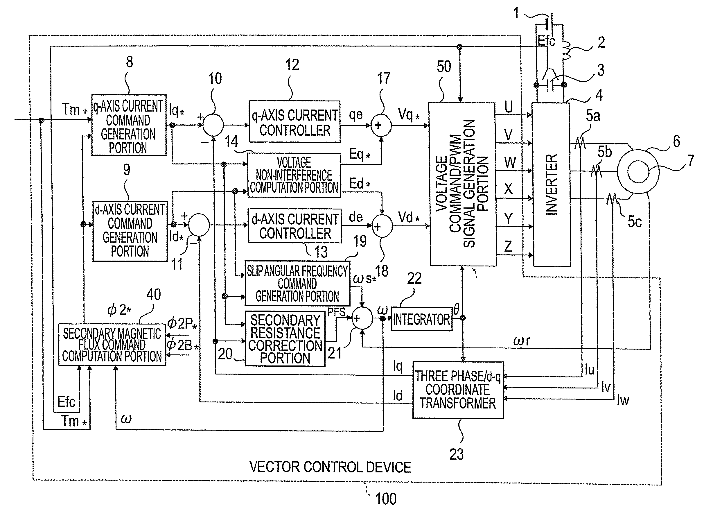
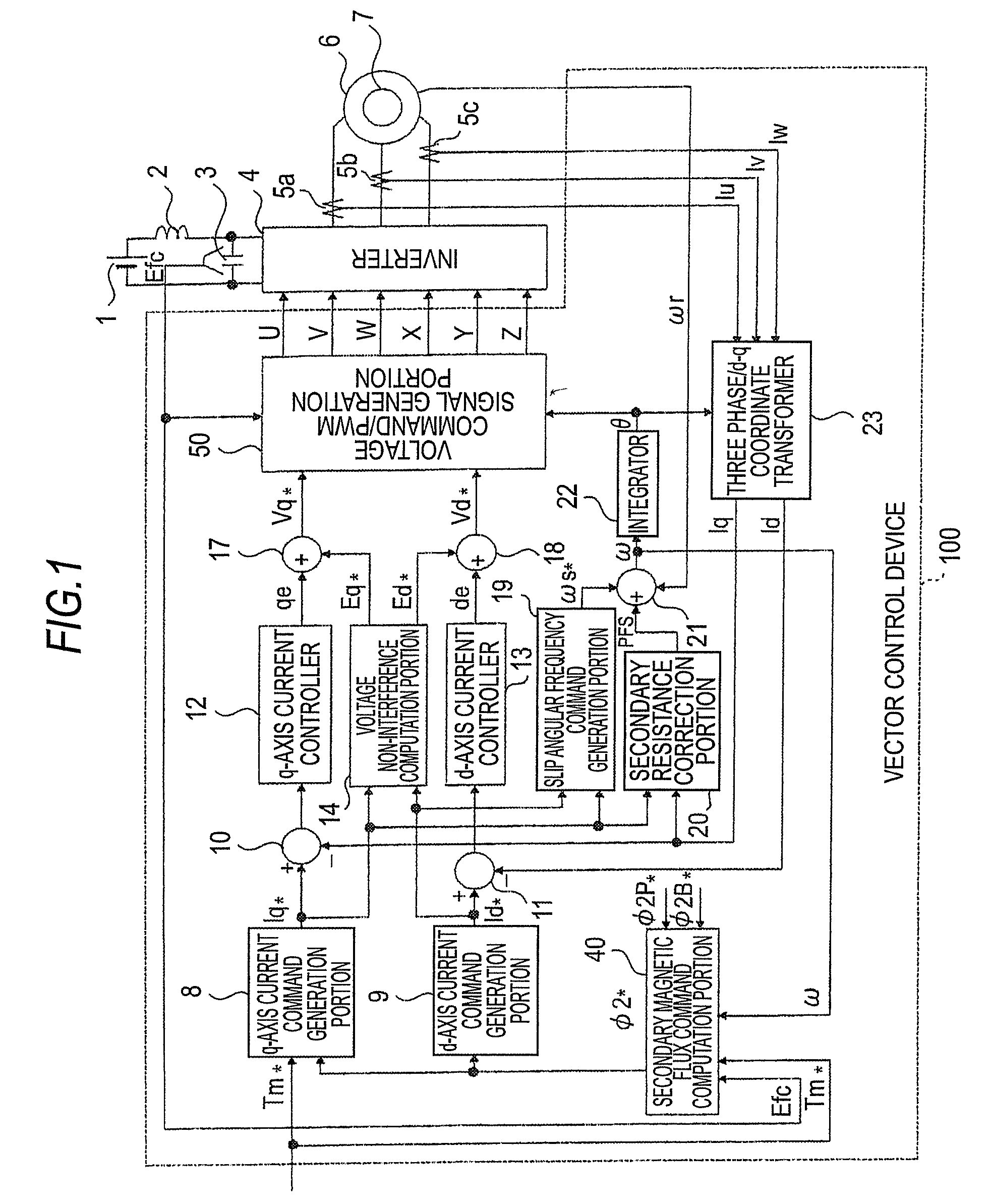
[0073]FIG. 1 is a block diagram showing an example of the configuration of a vector control device of an induction motor according to a first embodiment of the invention.

[0074]As is shown in the drawing, a main circuit has a DC power supply 1, an LC filter circuit formed of a reactor 2 and a capacitor 3 to suppress a harmonic current from flowing to the power supply side, an inverter 4 that converts a DC voltage Efc of the capacitor 3 to an AC voltage at an arbitrary frequency, and a vector control device 100 that performs vector control on an induction motor (hereinafter, referred to simply as the motor) 6.

[0075]It may be thought that the inverter 4 and the vector control device 100 together constitute a drive control device that controls the driving of the motor 6 by vector control.

[0076]The vector control device 100 is configured in such a manner that a signal from a speed detector 7 that detects a rotating speed of the motor 6, signals from current detectors 5a through 5c that d...


PUM


Abstract

The vector control device includes: secondary magnetic flux command computing means (40) for computing a secondary magnetic flux command to an induction motor (6) by taking a maximum voltage that an inverter (4) can generate into account on a basis of a torque command from an external, a DC voltage to be inputted into the inverter, and an inverter angular frequency, which is an angular frequency of an AC voltage to be outputted from the inverter; q-axis / d-axis current command generating means (8 and 9) for generating a q-axis current command and a d-axis current command on a d-q axes rotating coordinate system in reference to a secondary magnetic flux of the induction motor (6) on a basis of the torque command and the secondary magnetic flux command; output voltage computing means (voltage non-interference computation portion 14, adder 17, and adder 18) for computing an output voltage that the inverter (4) is to output on a basis of the q-axis current command, the d-axis current command, and a circuit constant of the induction motor (6); and voltage command / PWM signal generating means (50) for controlling the inverter (4) for the inverter (4) to output the output voltage.

Description

TECHNICAL FIELD[0001]The present invention relates to a vector control device of an induction motor connected to an inverter that converts a DC voltage to an AC voltage at an arbitrary frequency to output the AC voltage, a vector control method of an induction motor, and a drive control device of an induction motor.BACKGROUND ART[0002]A basic technique of vector control on an induction motor using an inverter is a prior art that has been used extensively in the industrial field. This technique is to control a torque of a motor instantaneously at a high speed through an operation of a torque component current in an orthogonal relation to a secondary magnetic flux inside the motor by operating the magnitude and the phase of an inverter output voltage separately.[0003]The vector control of an induction motor is a technique that is being used also in the electric railroad in recent years.[0004]A driving inverter of an electric vehicle is characterized in that the switching mode of the i...

Claims


Application Information

Patent Timeline
Patent Type & Authority Applications(United States)
IPC IPC(8): H02P27/08H02P23/07H02P21/00H02P27/04
CPCH02P21/0042H02P21/0092H02P21/12H02P21/06H02P21/02H02P21/26H02P21/36H02P21/04H02P27/04
Inventor KITANAKA, HIDETOSHINEGORO, HIDETO
Owner MITSUBISHI ELECTRIC CORP
Why Eureka
Try Eureka