Phase to digital converter in all digital phase locked loop

a phase lock and digital converter technology, applied in the field of oscillator and phase lock loop, can solve the problems of difficult design, difficult design, and difficult design of conventional analog pll, and achieve the effect of reducing the speed of the reference clock and power operation

Active Publication Date: 2009-10-15
QUALCOMM INC
View PDF5 Cites 125 Cited by
  • Summary
  • Abstract
  • Description
  • Claims
  • Application Information

AI Technical Summary

Benefits of technology

[0009]A phase to digital converter, all digital phase locked loop, and apparatus having an all digital phase locked loop are described herein. The phase to digital converter includes a phase to frequency converter driving a time to digital converter. The time to digital converter determines a magnitude and sign of the phase differences output by the phase to frequency converter. The time to digital converter ...

Problems solved by technology

At this low voltage, conventional analog building blocks such as operation amplifiers and current mirrors don't work well and are difficult to design.
Thus, a conventional analog PLL is difficult to design with such process.
In addition, an analog PLL typically needs large area to implement a filter function, while...

Method used


Image

  • Phase to digital converter in all digital phase locked loop
  • Phase to digital converter in all digital phase locked loop
  • Phase to digital converter in all digital phase locked loop

Examples


Embodiment Construction

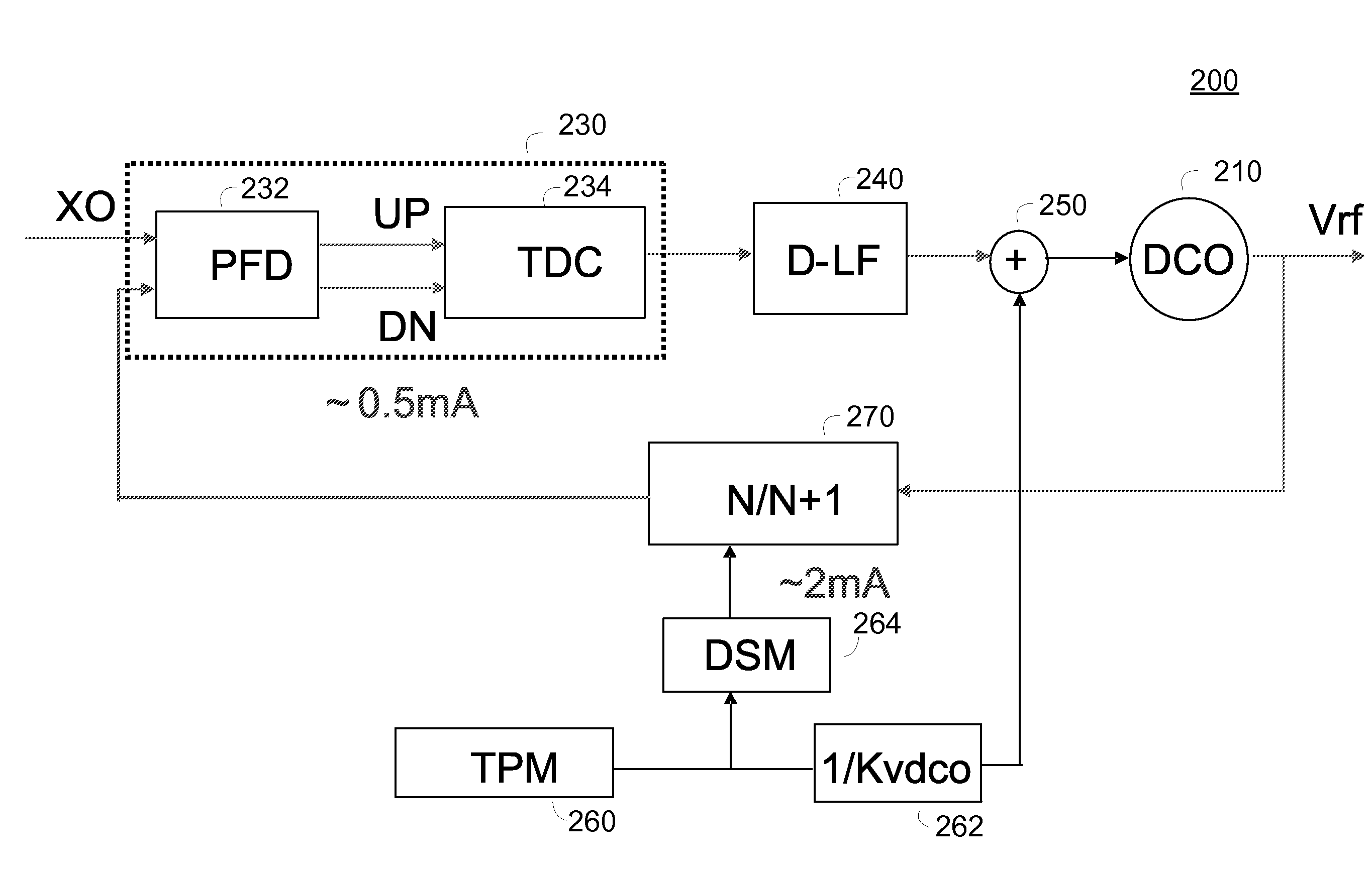
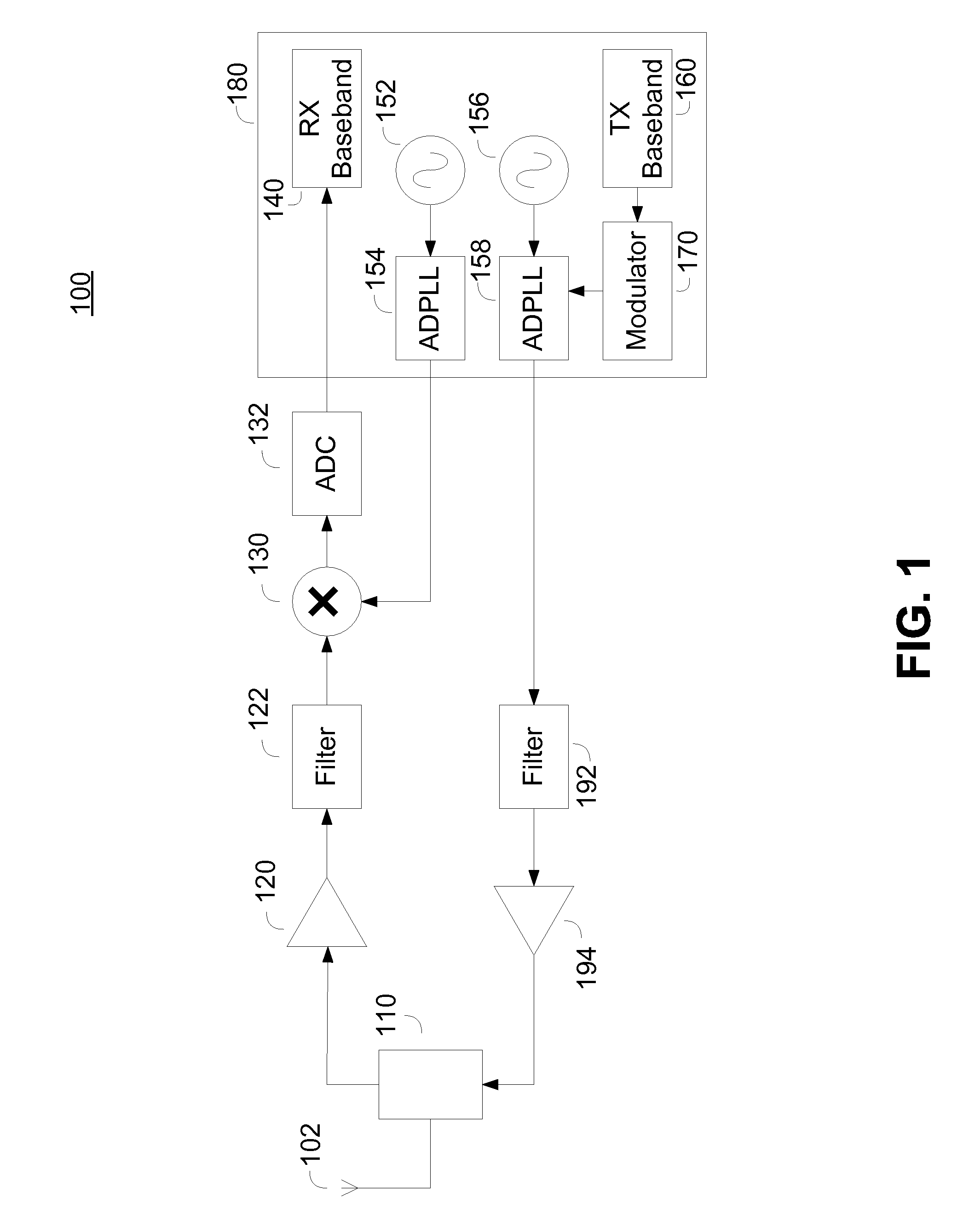
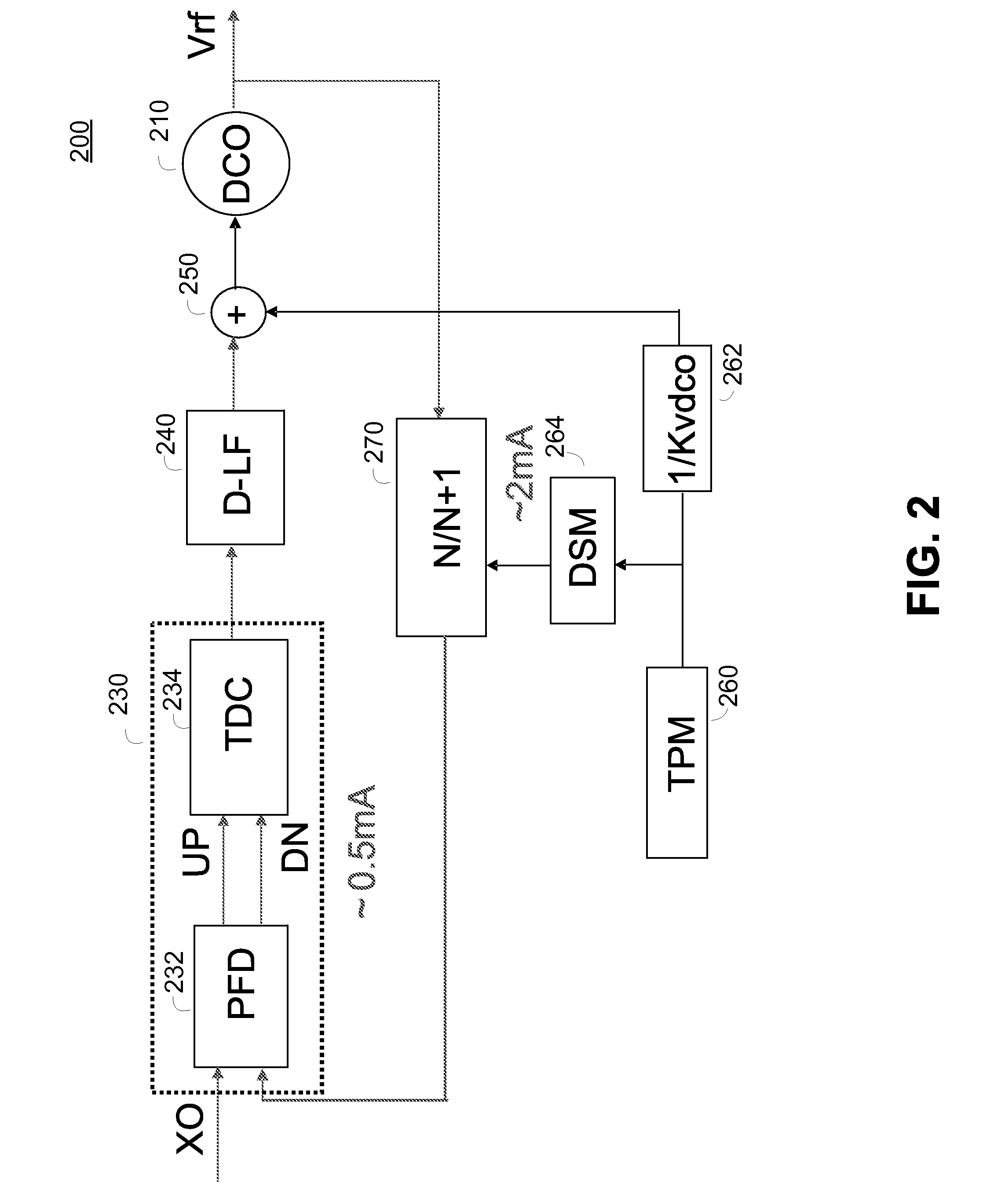
[0038]An All Digital Phase Locked Loop (ADPLL) is described herein that implements all PLL functions in digital circuitry with reduced silicon area and no off-chip components. The digital PLL can work at low power supply voltage. A phase to digital converter (PDC) design described herein forms a major operational block that enable the all digital PLL.

[0039]The proposed PDC converts analog phase information into a digital word which can in turn be fed into a digital signal processor. The PDC operates to convert the input phase information with fine resolution and high linearity, especially around the zero phase transition point. Due to device mismatches, a PDC may convert the positive phase and negative phase inputs with different gains or offsets. The different gains or offsets are equivalent to nonlinearity in a PDC conversion transfer function. This nonlinearity degrades overall PLL performance and operates ton increase phase noise and spurious response. The proposed ADPLL with PD...


PUM


Abstract

A phase to digital converter, all digital phase locked loop, and apparatus having an all digital phase locked loop are described herein. The phase to digital converter includes a phase to frequency converter driving a time to digital converter. The time to digital converter determines a magnitude and sign of the phase differences output by the phase to frequency converter. The time to digital converter utilizes tapped delay lines and looped feedback counters to enable measurement of small timing differences typical of a loop tracking process and large timing differences typical of an loop acquisition process. The tapped delay lines permit the measurement of fractions of a reference period and enable lower power operation of the phase to digital converter by reducing requirements on the speed of the reference clock.

Description

BACKGROUND[0001]1. Field of the Invention[0002]The invention relates to the field of electronic circuits. More particularly, the invention relates to the field of oscillators and phase locked loops (PLLs).[0003]2. Description of Related Art[0004]Phase and frequency controlled oscillators are used in a variety of electronic applications to provide stable, controlled, frequency references. A digital device may use a frequency controlled oscillator as a clock source for timing, for example, as a clock for a digital microprocessor circuit. An analog device may include a phase locked oscillator as a local oscillator used to frequency convert Radio Frequency (RF) signals. The phase and frequency controlled oscillator may be fixed frequency oscillator or may be a tunable oscillator that is implemented using a programmable frequency synthesizer.[0005]A frequency controlled oscillator for a digital device may be implemented digitally, while a phase locked oscillator for an analog device may ...

Claims


Application Information

Patent Timeline
IPC IPC(8): H03L7/06H03M1/48
CPCH03L7/085H03L2207/50H03L7/1976H03L7/089
Inventor ZHANG, GANGJAJOO, ABHISHEKHAN, YIPING
Owner QUALCOMM INC
Why Eureka
Try Eureka