Radar level gauge system with multi band patch antenna array arrangement

a technology of antenna array and radar, applied in the field of antenna arrangement, can solve the problems of affecting the accuracy of measurement, so as to avoid interference and achieve accurate measurement

Inactive Publication Date: 2009-10-15
ROSEMOUNT TANK RADAR
View PDF6 Cites 18 Cited by
  • Summary
  • Abstract
  • Description
  • Claims
  • Application Information

AI Technical Summary

Benefits of technology

[0010]According to the present invention, the reflector will be adapted to receive most of the radiation in the first and second radiation footprints. This results in an optimized antenna arrangement, where the amount of radiation energy emitted without reaching the reflector is reduced, while at the same time the full reflector size is used for all emitted frequency bands.

Problems solved by technology

Additionally, many liquids or tank conditions create a foam layer on the liquid or a layer of dirt on the antenna, whereby measuring is rendered more difficult and may go wrong.

Method used


Image

  • Radar level gauge system with multi band patch antenna array arrangement
  • Radar level gauge system with multi band patch antenna array arrangement
  • Radar level gauge system with multi band patch antenna array arrangement

Examples


Embodiment Construction

[0022]In the present detailed description, reference is mainly made to filling level determination by means of measuring the time between transmitted and reflected pulses. However, as is evident to the person skilled in the relevant art, the teachings of the present invention are equally applicable to radar level gauge systems utilizing phase information for determining the filling level through, for example, frequency-modulated continuous wave (FMCW) measurements. When pulses modulated on a carrier are used, phase information can also be utilized.

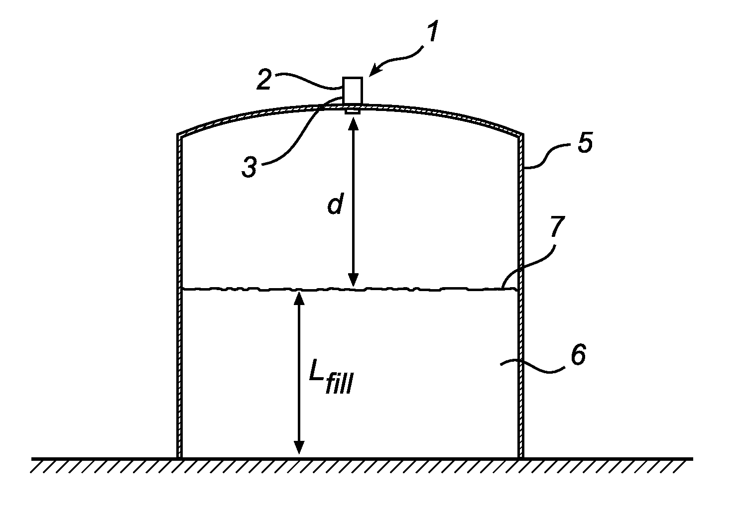
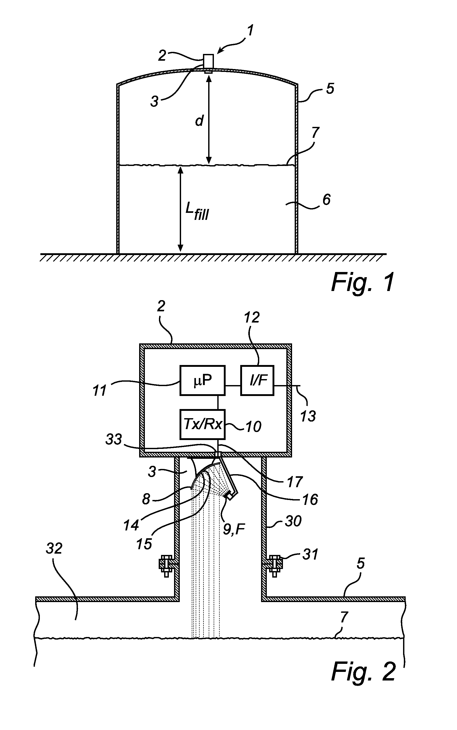
[0023]FIG. 1 schematically illustrates a radar level gauge system 1, according to an exemplary embodiment of the present invention, comprising a measurement electronics unit 2 and an antenna arrangement 3. The radar level gauge system 1 is mounted on a flange 30 of a tank 5, by bolts 31 or any other means considered appropriate for the current conditions. The RLG (Radar Level Gauge), and thus the antenna arrangement 3, is thereby secured i...


PUM


Abstract

A radar level gauge system (1) having an antenna arrangement (3) adapted to emit microwaves towards a surface (7) of the product (6) and to receive microwaves reflected from the surface (7) The antenna arrangement (3) includes a reflector (8) and a multi band patch antenna array (9) arranged at a distance from the reflector (8) and adapted to emit electromagnetic waves to be reflected by the reflector towards the surface (6). The array (9) has first and second groups of radiator elements (19) adapted to emit electromagnetic radiation with first and second radiation footprints (14, 15), wherein the second radiation footprint (15) is substantially equal to the first radiation footprint (14), and wherein the reflector (8) has a size corresponding to the first and second radiation footprints (14, 15).According to the present invention, the reflector will be adapted to receive most of the radiation in the first and second radiation footprints. This results in an optimized antenna arrangement, where the amount of radiation energy emitted without reaching the reflector is reduced, while at the same time the full reflector size is used for both frequency bands.

Description

TECHNICAL FIELD OF THE INVENTION[0001]The present invention relates to an antenna arrangement adapted to, on at least one first frequency band and at least one second frequency band, transmit microwaves towards a surface of a product stored in a tank and receiving microwaves reflected from the surface.BACKGROUND ART[0002]Radar level gauge systems are in wide use for measuring process variables of a product contained in a tank, such as filling level, ullage or volume. Radar level gauging is generally performed by means of non-contact measurement, whereby electromagnetic signals are allowed to propagate freely towards the product contained in the tank. The electromagnetic signals are subsequently reflected at the surface of the product, and the reflected signals are received by a receiver or transceiver comprised in the radar level gauge system. Based on the transmitted and reflected signals, the distance to the surface of the product can be determined.[0003]Radar level gauges for use...

Claims


Application Information

Patent Timeline
Patent Type & Authority Applications(United States)
IPC IPC(8): H01Q9/04G01S13/08
CPCG01F23/284G01S7/282H01Q21/065G01S13/88H01Q1/225G01S7/35
Inventor OHLSSON, MAGNUS
Owner ROSEMOUNT TANK RADAR
Why Eureka
Try Eureka