Nonvolatile analog memory

Active Publication Date: 2009-10-15
NATIONAL TSING HUA UNIVERSITY
View PDF3 Cites 8 Cited by
  • Summary
  • Abstract
  • Description
  • Claims
  • Application Information

AI Technical Summary

Benefits of technology

[0013]In the present invention, the adjustment of the currents enables analog signals to be written into the nonvolatile analog memory. Hence, the data can be stored in an accurate manner. Additionally, the voltage value stored in the nonvolatile analog memory is

Problems solved by technology

However, one of the common issues encountered by the aforesaid digital memories lies in that one memory cell is required for correspondingly storing each bit of data.
The increasing dimensions of the memories lead to difficulties not only in designing

Method used


Image

  • Nonvolatile analog memory
  • Nonvolatile analog memory
  • Nonvolatile analog memory

Examples


Example

[0027]A first embodiment of the present invention is provided hereinafter along with drawings to describe an operational manner of a nonvolatile analog memory.

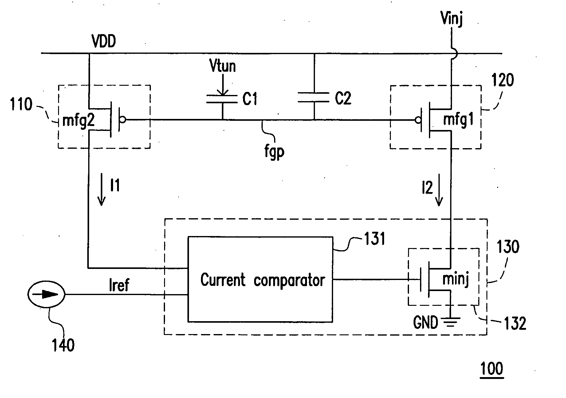
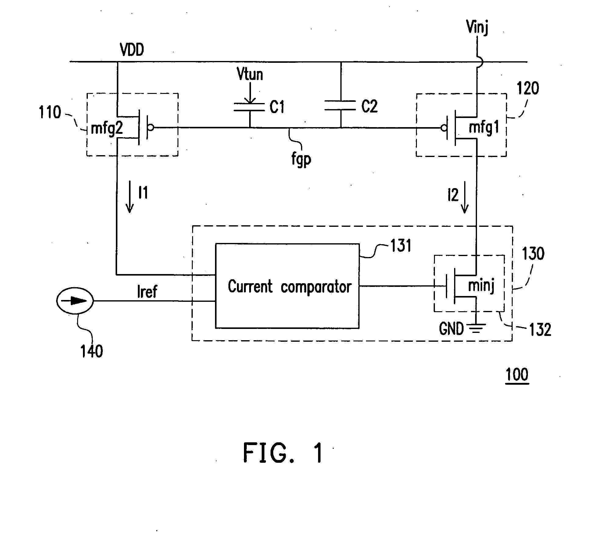
[0028]Please refer to FIG. 1 which is a schematic view of a nonvolatile analog memory 100 according to the first embodiment of the present invention The nonvolatile analog memory 100 includes a current source 110, a current source 120, a current adjuster 130, capacitors C1 and C2, and a reference current source 140.

[0029]In the first embodiment, the current source 110 is formed by a transistor mfg2. A first source / drain of the transistor mfg2 is coupled to a system voltage VDD. A gate of the transistor mfg2 is controlled by a voltage applied to a floating gate point fgp, and a current I1 is generated at a second source / drain of the transistor mfg2. By contrast, the current source 120 is formed by a transistor mfg1. A first source / drain of the transistor mfg1 is coupled to a voltage Vinj. A gate of the transistor mfg1 is contro...

Example

Second Embodiment

[0043]To allow people skilled in the art to better recognize and embody the present invention, a second embodiment is detailed in following paragraphs.

[0044]Please refer to FIG. 5 which is a schematic view of a nonvolatile analog memory 500 according to the second embodiment of the present invention The nonvolatile analog memory 500 includes current sources 510 and 520, a current adjustor 530, and a capacitor Cc. The current adjustor 530 includes a comparator COMP1, switches 532 and 533, and current sources 531 and 534. The current sources 510 and 520 are respectively constituted by transistors mfg1 and mfg2. Here, both of the current sources 510 and 520 are controlled by a voltage value at a floating gate point fgp and respectively generate currents I1 and I2.

[0045]The current adjustor 530 disables / enables the switches 532 and 533 by using the comparator COMP1 to compare a feedback voltage Vout with a reference voltage Vref. According to the second embodiment, the ...


PUM


Abstract

A nonvolatile analog memory has a floating gate point. The nonvolatile analog memory includes a first current source, a second current source, and a current adjuster. The first current source generates a first current, and the second current source generates a second current. The current adjuster turns on or turns off a current path of the second current according to a reference current and the first current. Furthermore, when the current path of the second current is turned on, the first current is adjusted according to the second current, such that the first current is equal to the reference current.

Description

CROSS-REFERENCE TO RELATED APPLICATION[0001]This application claims the priority benefit of Taiwan application serial no. 97113243, filed on Apr. 11, 2008. The entirety of the above-mentioned patent application is hereby incorporated by reference herein and made a part of this specification.BACKGROUND OF THE INVENTION[0002]1. Field of the Invention[0003]The present invention relates to a memory. More particularly, the present invention relates to a nonvolatile analog memory.[0004]2. Description of Related Art[0005]With an advancement of electronic technologies, electronic devices have become indispensable in our daily lives. Owing to increasing demands on information, almost all of the electronic devices currently on the market are equipped with memories for data storage. In the past, various digital memories have been widely proposed. The digital memories include dynamic random access memories (DRAMs) and read only memories (ROMs).[0006]However, one of the common issues encountered...

Claims


Application Information

Patent Timeline
IPC IPC(8): G11C27/00G11C16/06G11C7/00
CPCG11C27/005G11C16/0441
Inventor HUANG, CHENG-DALU, CHIH-CHENGCHEN, HSIN
Owner NATIONAL TSING HUA UNIVERSITY
Why Eureka
Try Eureka