Fixing device and image forming apparatus including the same

Active Publication Date: 2009-10-15
SHARP KK
View PDF6 Cites 2 Cited by
  • Summary
  • Abstract
  • Description
  • Claims
  • Application Information

AI Technical Summary

Benefits of technology

[0037]According to the invention, an image forming apparatus includes the fixing device capable of uniforming distribution of a temperature in the longitudinal direction of the heating member and of attaining uniform fixing capability in the fixing ni

Problems solved by technology

However, in a fixing roller having an elastic layer, the elastic layer can not sufficiently conduct heat, thus, in a case where a heating section is provided inside the fixing roller, there is a problem that a temperature of the fixing roller is not followed when a process speed is increased.
On the other hand, when a diameter of the fixing roller is increased, there is a problem that it takes longer time to warm up or power consumption is increased.
Accordingly, the temperature of the both ends of the planar heat generating element is lower than that of a center part and it is difficult to obtain uniform temperature distribution over the all areas in a longitudinal direction.
As a result, when such a fixing device is applied to an image forming apparatus such as a copier and a printer, variance is generated in a toner fixing temperature and the printing quality is deteriorated,
That is, when the planar heat generating element does not have a self-temperature-controlling function (positive resistance temperature characteristic), during continuous printing of recording sheets having different sizes, a temperature of a non-sheet passing part is excessively increased in the heating roller, thus a step of reducing the temperature of the heating roller to an appropria

Method used


Image

  • Fixing device and image forming apparatus including the same
  • Fixing device and image forming apparatus including the same
  • Fixing device and image forming apparatus including the same

Examples


Example

Example 1

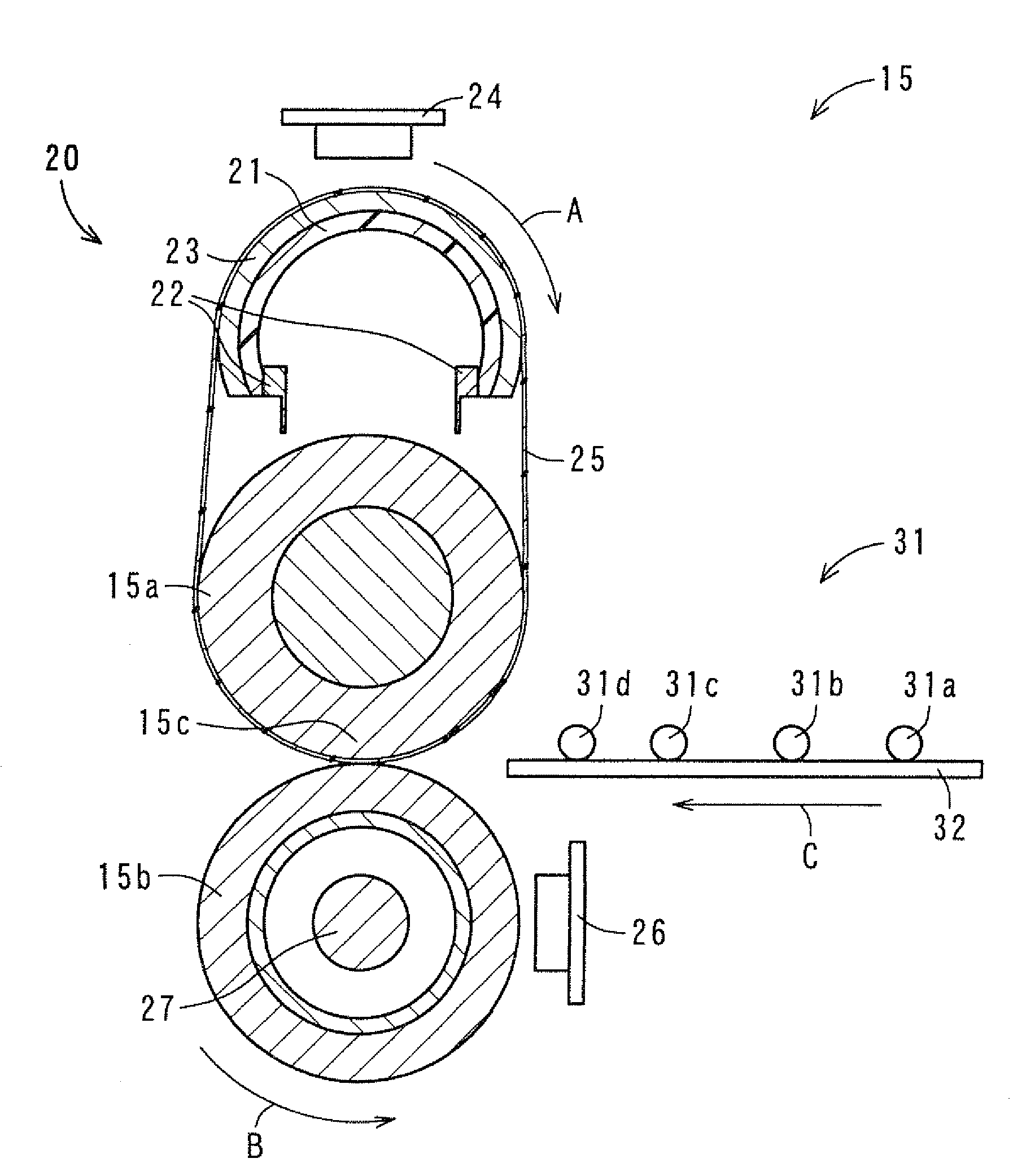
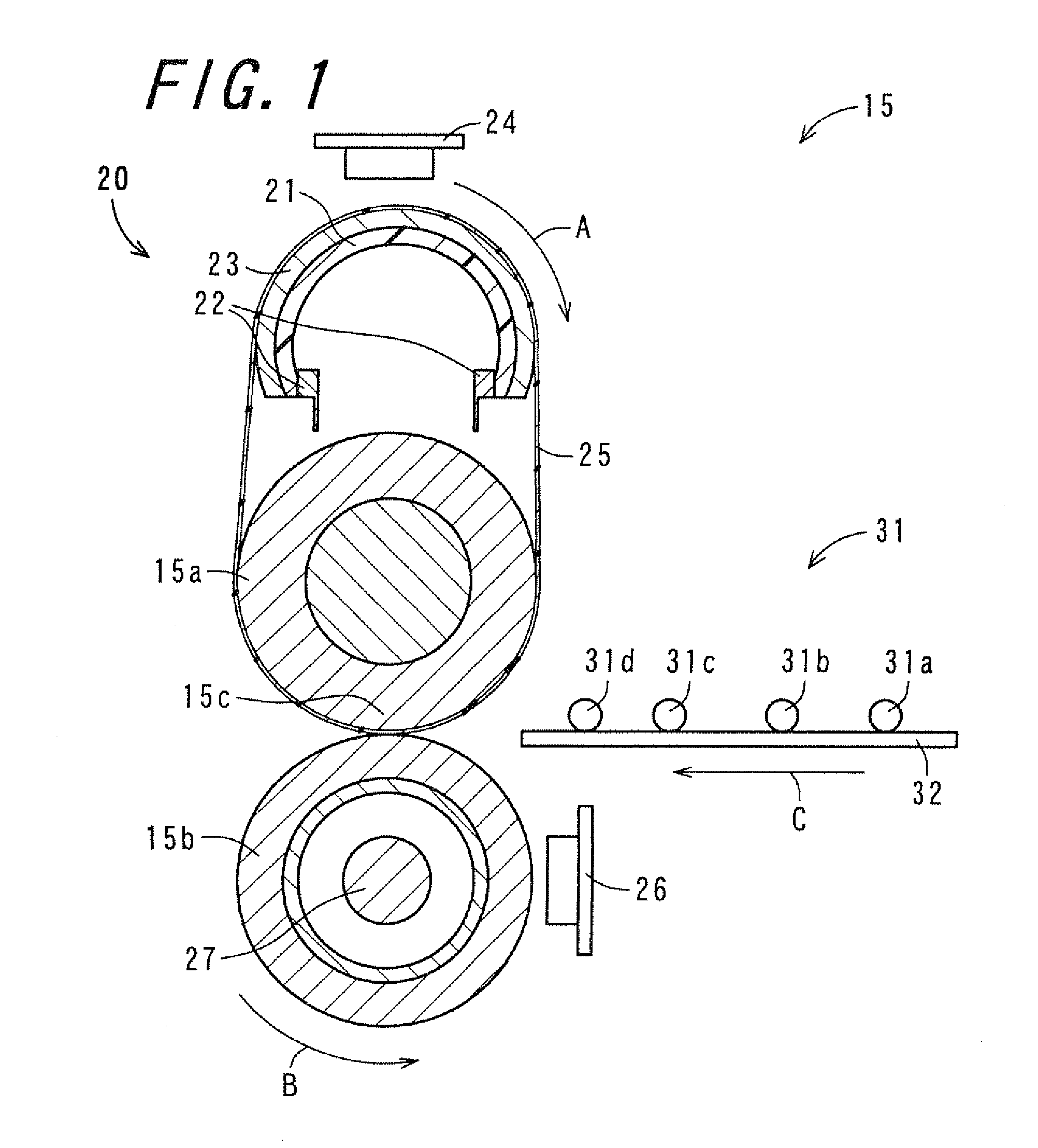
[0110]A fixing device used in Example 1 was the above-described fixing device 15. The detailed condition in Example 1 was as follows.

[0111]

[0112]Used was a fixing roller that had a diameter of 30 mm in which stainless steel having a diameter of 15 mm was used as a core metal and silicone sponge rubber having thickness of 7.5 mm was used as an elastic layer.

[0113]

[0114]Used was a pressure roller that had a diameter of 30 mm and was made of silicone solid rubber, in which PFA tube having thickness of 30 μm was used as a release layer and a heater lamp having a rated power of 400 W was disposed inside.

[0115]

[0116]Used was a fixing belt in which polyimide having thickness of 70 μm was used as a belt substrate, silicone rubber having thickness of 150 μm was used as an elastic layer, and PFA tube having thickness of 30 μm was used as a release layer, and whose winding angle θ was 185°.

[0117]

[0118]A polyphenylene sulfide (PPS) collar having an inner diameter of 20 mm, a diameter o...

Example

Example 2

[0135]A fixing device used in Example 2 was the above-described fixing device 35. Example 2 was conducted in the similar manner to Example 1 except that the heating member was different.

[0136]

[0137]A polyimide layer of 30 μm as an insulating layer was formed on an outer surface of a substrate made of an aluminum pipe having thickness of 1 mm and provided with steps at both ends thereof, and on the outer surface thereof, a composite material in which graphite particles were dispersed in a silicone resin (3.3 parts by weight of graphite particles relative to 1 part by weight of a silicone resin) was formed as a heat generating layer so that an area of a center part in the longitudinal direction had thickness of 0.5 mm and 30 mm of both ends thereof had thickness of 0.6 mm. In addition, as a coat layer of the outermost layer, a fluorine resin having thickness of 20 μm was coated. The others were similar to Example 1.

[0138]Heat generated from the planar heat generating element ...

Example

Example 3

[0140]A fixing device used in Example 3 was the above-described fixing device 45. Example 3 was conducted in the similar manner to Example 1 except that the heating member was different.

[0141]

[0142]The heating member was obtained by shaping, as a heat generating layer, semiconductor ceramics based on barium titanate with Curie temperature of 250° C. into a semicircular roller shape so as to have an external diameter of 28 mm, thickness of 2 mm, and a length in an axial direction of 350 mm; and providing, on the surface of which, a coat layer made of a fluorine resin having thickness of 20 μm used in Example 1. At this time, thickness of the heat generating layer was set so that both ends in a longitudinal direction thereof had larger thickness than that of a center part thereof, similarly to Example 1. Except for the heating members the others were similar to Example 1.

[0143]In the heating member of Example 3, heat generated from the heat generating layer was not transmitte...


PUM


Abstract

A fixing device is provided that suppresses loss in heat radiation from both ends in a longitudinal direction which is a direction corresponding to an axial direction of a fixing roller in a heating member so as to be able to uniform distribution of a temperature in the longitudinal direction of the heating member and to attain uniform fixing capability. A planar heat generating element provided in a heating member includes electrodes at both ends in a circumferential direction so that a flowing direction of current flowing through the planar heat generating element is a direction substantially orthogonal to a longitudinal direction as a direction extending along an axial direction of a fixing roller in the planar heat generating element. The planar heat generating element is constituted so that the both ends in the longitudinal direction thereof have larger thickness than that of a center part thereof.

Description

CROSS-REFERENCE TO RELATED APPLICATION[0001]This application claims priority to Japanese Patent Application No. 2008-105100, which was filed on Apr. 14, 2008, the contents of which are incorporated herein by reference in its entirety.BACKGROUND OF THE INVENTION[0002]1. Field of the Invention[0003]The present invention relates to a fixing device for fixing a toner image to a recording medium with heat and pressure and an image forming apparatus including the fixing device.[0004]2. Description of the Related Art[0005]As a fixing device for use in an electrophotographic image forming apparatus such as a copying machine and a printer, a fixing device of heat-roller fixing type has been in wide use. The heat-roller fixing-type fixing device includes a pair of rollers (a fixing roller and a pressure roller) that is brought into contact with each other under pressure. By means of a heating section composed for example of a halogen heater, which is placed in each of or one of the pair of ro...

Claims


Application Information

Patent Timeline
IPC IPC(8): G03G15/20
CPCG03G2215/2029G03G15/2053
Inventor KAGEYAMA, HIROYUKI
Owner SHARP KK
Why Eureka
Try Eureka