Article and method of manufacture thereof

a technology of damping and parts, applied in the field of damping parts, can solve the problems of limiting the location of the component on which the damper is mounted, affecting the efficiency of the damping, and requiring a large, heavier and less efficient damper

Inactive Publication Date: 2009-10-15
ROLLS ROYCE PLC
View PDF7 Cites 58 Cited by
  • Summary
  • Abstract
  • Description
  • Claims
  • Application Information

AI Technical Summary

Benefits of technology

[0015]With the present invention, the method of manufacture can create cooling channels that can actively cont

Problems solved by technology

Where the outside form of the component is important for perhaps aerodynamic, thermal or geographic reasons, such particle dampers may be difficult to use.
Additionally, the method of attaching the damper limits the locations of the component on which t

Method used


Image

  • Article and method of manufacture thereof
  • Article and method of manufacture thereof
  • Article and method of manufacture thereof

Examples


Embodiment Construction

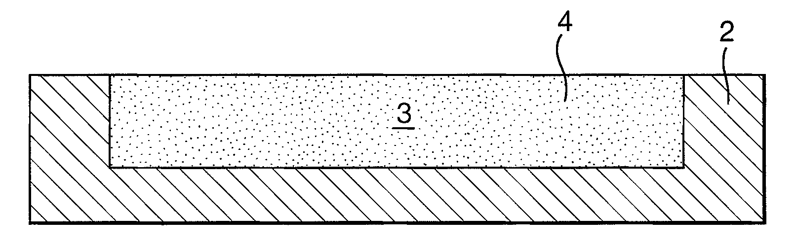
[0028]In a first embodiment the article 2, which may be an article used in a turbine engine, is formed or partly formed using a direct manufacturing technique such as direct laser deposition. The article may be a fuel injector or combustor casing or other appropriate component that requires vibration damping.

[0029]The article 2 is formed in a layerwise manner using a deposition head. The preferred deposition head can deliver a high-energy beam, typically a laser beam, and a feedstock, typically powder, to a substrate. The deposition head is mounted to a movement means such as a robotic arm and can traverse over the substrate in a pre-programmed path.

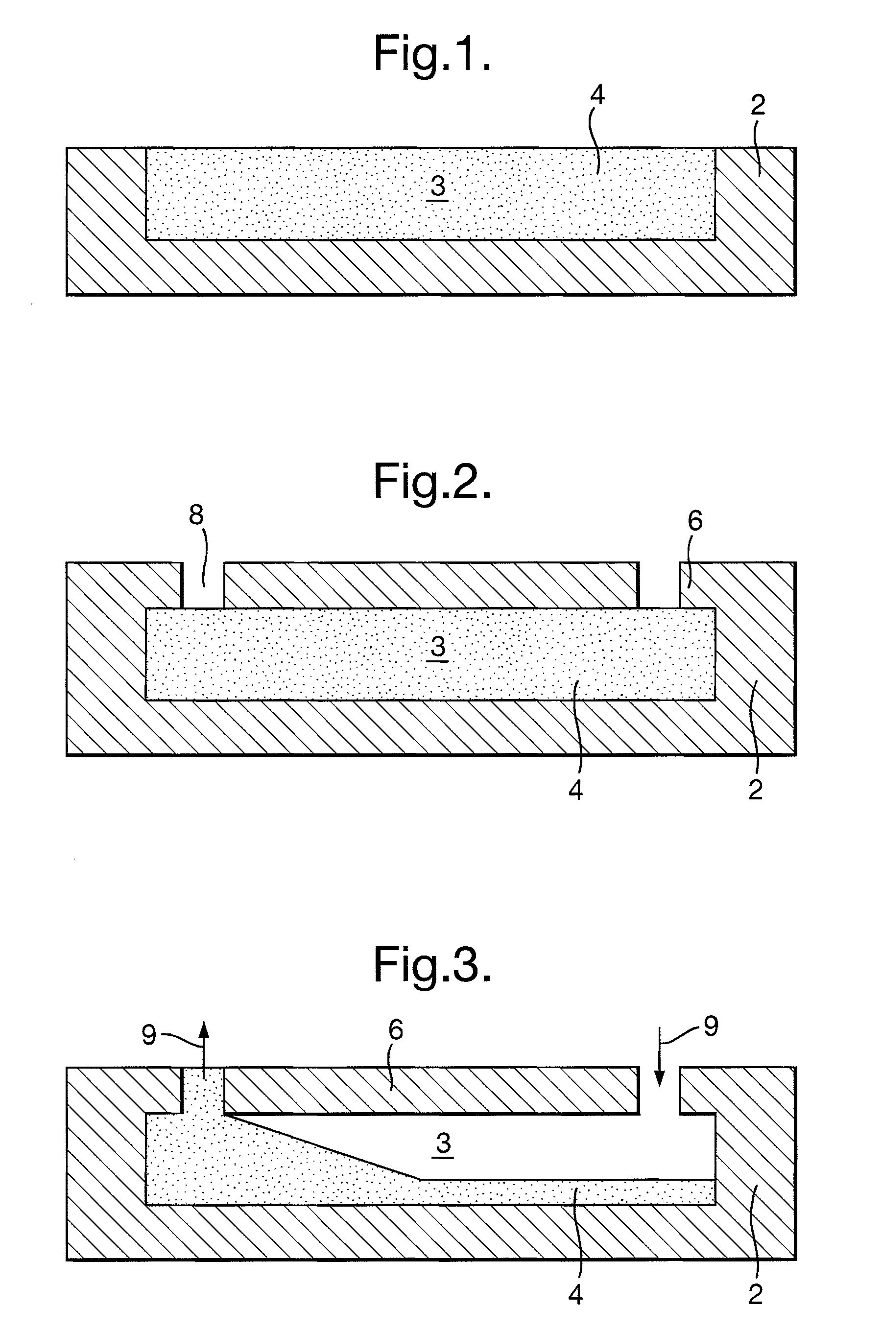
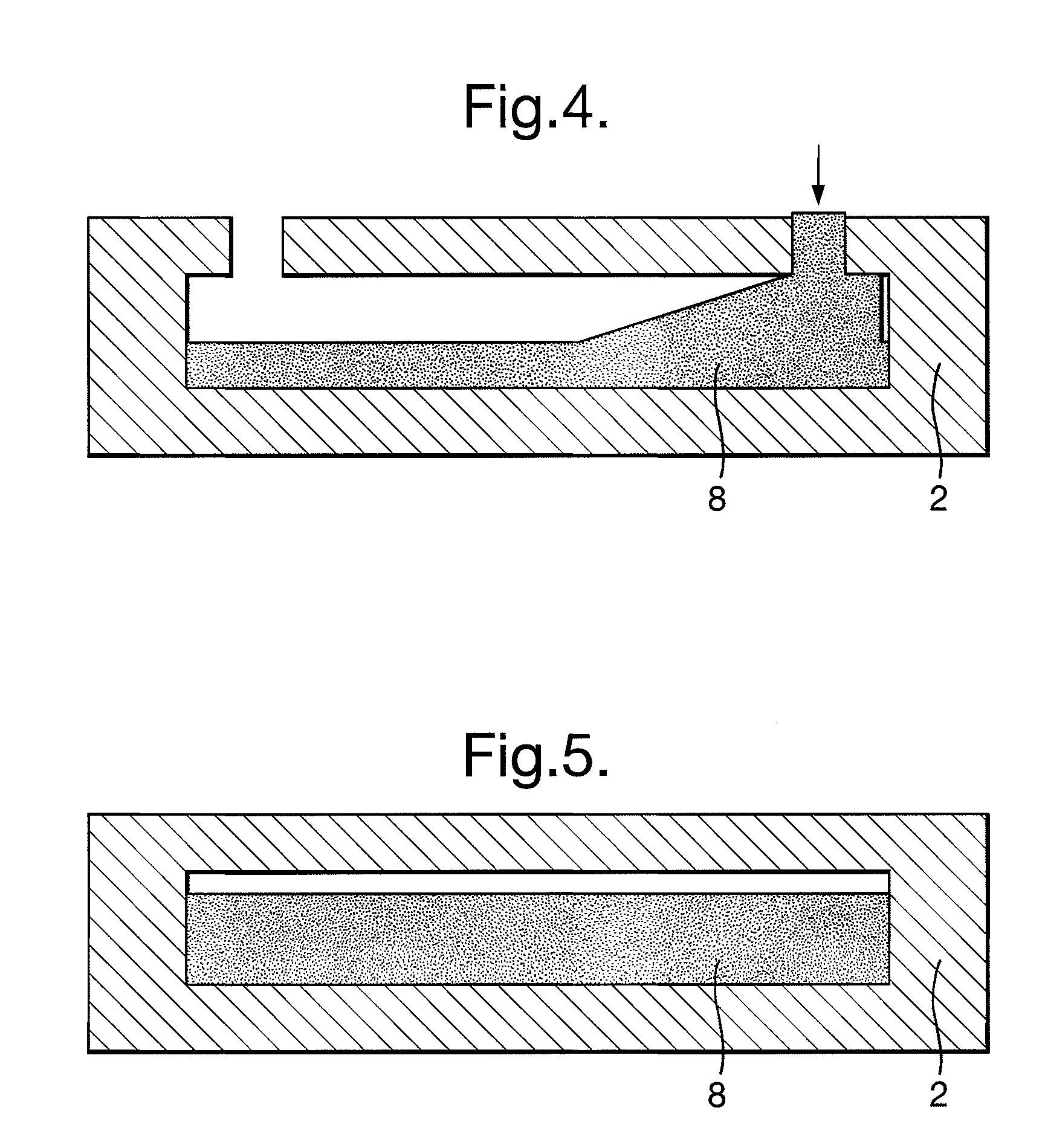
[0030]As the deposition head traverses over the substrate in the pre-programmed path the laser selectively melts a portion of the substrate and forms a melt pool. Powder is directed from the deposition head into the melt pool and is melted either in the melt pool or by the heat of the laser. Once the laser has traversed from the melt poo...


PUM

PropertyMeasurementUnit
Fractionaaaaaaaaaa
Fractionaaaaaaaaaa
Fractionaaaaaaaaaa

Abstract

A particle damper is formed using a solid freeform manufacturing technique. A filler provides support for the closing wall of the cavity as it is formed. Apertures allow at least a portion of the filler to be removed. A particle fill of between 90 and 95% is achieved either by removing sufficient filler to reach this fill or removing excess filler and re-filling with damping particles.

Description

CROSS REFERENCE TO RELATED APPLICATION[0001]This application is entitled to the benefit of British Patent Application No. GB 0806768.8, filed on Apr. 15, 2008.FIELD OF THE INVENTION[0002]This invention relates to articles used for damping and the method of manufacture thereof.BACKGROUND OF THE INVENTION[0003]Dampers, known as particle vibration dampers are known from U.S. Pat. No. 6,547,049. These dampers comprise a hollow volume filled with particles up to around 95% volume fill. As explained in this patent, the particle vibration damper operates by particle interface contact friction whereby the frictional forces are dependent upon material type and contact forces, the contact forces being governed by the vibratory accelerations of the wall. Under specific vibrations a particle will attempt to migrate through the vibration damper device in a direction that is generally parallel to the polar axis and competes with the other particles for their migratory position. Three analogous ph...

Claims


Application Information

Patent Timeline
IPC IPC(8): B05D5/00
CPCB22F3/1055B22F5/10F16F1/37B29L2031/721B29C67/0051Y10T29/4932Y10T29/4933Y10T29/49801Y02P10/25B22F10/25B22F10/43B22F10/28B22F10/50F16F7/01B29C64/40
Inventor BARCOCK, CARL LEECARLISLE, MICHAEL LAWRENCEGARRY, IAN MURRAYCLARK, DANIELYOUNG, GEMMA LOUISE
Owner ROLLS ROYCE PLC
Why Eureka
Try Eureka