Method for managing a torque applied to an output shaft of a combustion engine when one combustion chamber is deactivated, and corresponding management system

a technology of output shaft and combustion engine, which is applied in the direction of analogue computers, electric energy vehicles, analog and hybrid computing, etc., can solve the problems of relatively large operating noise, unsatisfactory results, and likely vibration of the output shaft, so as to reduce the jump in torque, minimize imbalance, and prevent any sudden variation in torque

Active Publication Date: 2009-10-15
VALEO SYST DE CONTROLE MOTEUR
View PDF7 Cites 11 Cited by
  • Summary
  • Abstract
  • Description
  • Claims
  • Application Information

AI Technical Summary

Benefits of technology

[0007]It has been found that the management of the transitional phases by the anticipation of a change in the resultant torque applied to the output shaft prior to the deactivation reduces the jump in torque at the moment of deactivation and of reactivation, which minimizes the imbalance to which the output shaft is subjected according to a first-order compensation.
[0008]According to an advantageous version of the invention, the compensating torque is also applied after the deactivation of the combustion chamber. This prevents any sudden variation in the torque applied to the output shaft at the moment of deactivation, which again minimizes the imbalance during the deactivation of the combustion chamber.
[0009]According to another advantageous aspect of the invention, the method also comprises the step of applying to the output shaft a correction torque compensating for an imbalance of the output shaft. This therefore manages to dampen the imbalance according to a correction of second order so that the resultant torque becomes stable virtually throughout the combustion chamber deactivation phase.
[0017]The alternator starter is then operated to draw off torque from the output shaft or to supply an additional torque to the output shaft making it possible to compensate for the imbalance. The alternator starter allows a particularly fast and effective compensation of the imbalances.
[0019]The control of the rotating machine is then relatively simple.

Problems solved by technology

The deactivation of one or more combustion chambers however has the disadvantage of creating an imbalance of the output shaft that is likely to produce vibrations and relatively considerable operating noises.
This imbalance is however less sensitive if the combustion chambers are numerous, so that the deactivation of the combustion chambers is used only in engines with large cubic capacity.
However, the results obtained are not very satisfactory.

Method used


Image

  • Method for managing a torque applied to an output shaft of a combustion engine when one combustion chamber is deactivated, and corresponding management system
  • Method for managing a torque applied to an output shaft of a combustion engine when one combustion chamber is deactivated, and corresponding management system
  • Method for managing a torque applied to an output shaft of a combustion engine when one combustion chamber is deactivated, and corresponding management system

Examples


Embodiment Construction

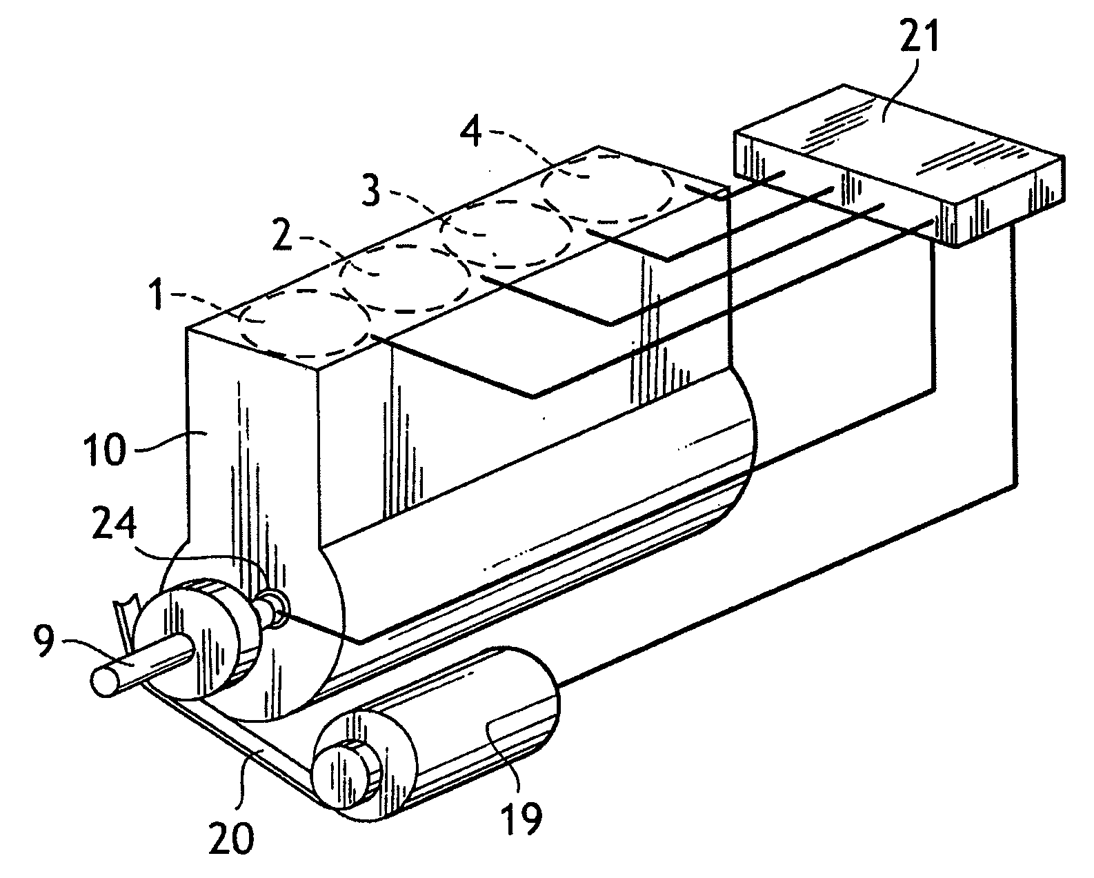
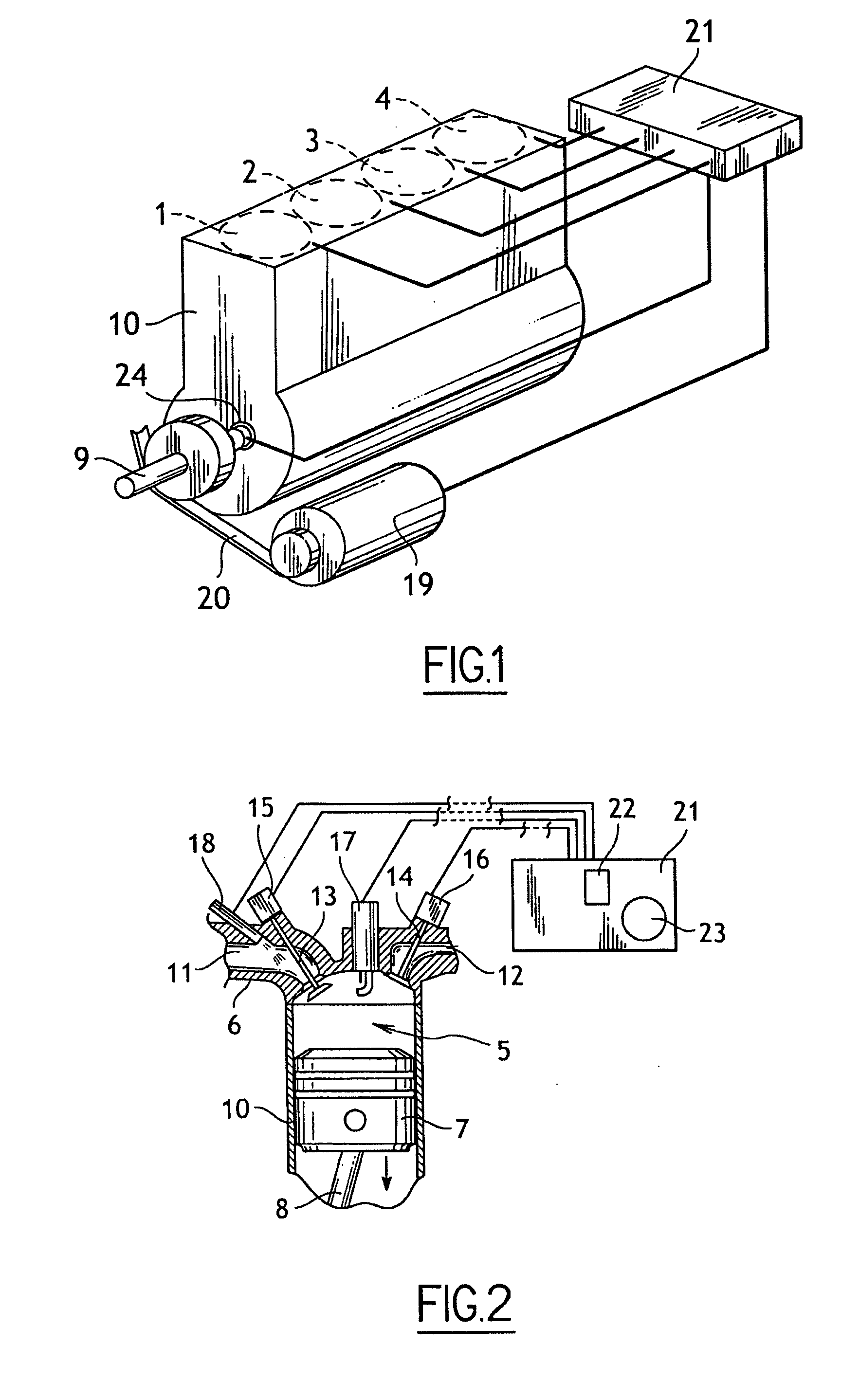
[0030]With reference to the figures, the heat engine according to the invention comprises a block 10 delimiting four in-line cylinders 1, 2, 3, 4. Each cylinder 1, 2, 3, 4 defines a chamber 5 closed on one side by a cylinder head 6 and on the other side by a piston 7 that can be moved slidingly in the cylinder 1, 2, 3, 4 between two extreme positions (top dead center and bottom dead center) and connected via a connecting rod 8 to a crankshaft 9 mounted pivotingly in the block 10.

[0031]An inlet duct 11 and an exhaust duct 12 that are arranged in the cylinder head 6 lead into each combustion chamber 5. The inlet duct 11 and the exhaust duct 12 are fitted respectively with an inlet valve 13 and an exhaust valve 14 moved between two positions, open and closed, by electromagnetic actuators 15, 16 respectively.

[0032]A spark plug 17 is mounted on the cylinder head 6 in order to lead into the combustion chamber 5. The spark plug 17 is connected to an ignition circuit known per se and not sh...


PUM


Abstract

A method for managing a torque applied to an output shaft of a combustion engine, the combustion engine including combustion chambers, in each of which there is mounted a piston connected to the output shaft in order to apply a torque to it, the output shaft being connected to a rotary machine associated with a management member. The method involves detecting conditions of deactivation of one combustion chamber and controlling the rotary machine so as to apply to the output shaft, prior to the deactivation of one combustion chamber, a compensating torque which tends to cause a resultant torque applied to the output shaft to tend towards a deactivation torque applied by the combustion engine to the output shaft after deactivation of the combustion chamber.

Description

[0001]The present invention relates to a method for managing a torque applied to an output shaft of a heat engine when a combustion chamber is deactivated, and a corresponding management system.BACKGROUND OF THE INVENTION[0002]A heat engine of a motor vehicle usually comprises cylinders delimiting combustion chambers in each of which is mounted a piston connected to an output shaft (or crankshaft) in order to apply a torque thereto. The output shaft is itself connected, via the gearbox, to wheels of the vehicle in order to rotate the latter. The output shaft is also connected to one or more auxiliary rotating machines such as the alternator in order to produce the electricity consumed onboard the vehicle.[0003]There exist engines also comprising a member for managing a deactivation of one or more of the combustion chambers. Such engines with combustion chambers that can be deactivated usually comprise at least 8 combustion chambers. The deactivation of one or more combustion chamber...

Claims


Application Information

Patent Timeline
Patent Type & Authority Applications(United States)
IPC IPC(8): F02D45/00F02D17/02
CPCB60K6/485B60W2710/0666F02D13/06F02D41/0087Y02T10/6226F02D41/307F02D2250/21F02D2250/24F02D41/1498Y02T10/62
Inventor PICRON, VANESSAROCHETTE, CLAUDINEVASILESCU, CLAUDIUGIRARDIN, ANTHONYBIZET, BENOIT
Owner VALEO SYST DE CONTROLE MOTEUR
Why Eureka
Try Eureka