Method for Operating an Electromagnetic Flowmeter and Electromagnetic Flowmeter

Active Publication Date: 2009-10-22
SIEMENS AG
View PDF7 Cites 9 Cited by
  • Summary
  • Abstract
  • Description
  • Claims
  • Application Information

AI Technical Summary

Benefits of technology

[0013]In an advantageous manner, exemplar-specific compensation of the offset error caused by an unstable magnetic field is made possible if, on the basis of the measured voltage applied to the coil arrangement, according to a predetermined relation, a correction value is calculated by which the voltage detected at the measuring electrodes is corrected for measurement value determination. This predetermined functional relation is preferably determined at the flowmeter itself at an earlier time point, preferably at start-up. It is stipulated as a parameterized linear

Problems solved by technology

Since there is a significant delay between the coil current and the magnetic field generated, knowledge of the current strength alone is not a sufficient measure of the strength of the magnetic field.
If this lies outside a permissible tolerance range, the magnetic field has not yet stabilized sufficiently.
Offset errors can, in principle, have various different causes, for example, resistive, capacitive and inductive coupling between th

Method used


Image

  • Method for Operating an Electromagnetic Flowmeter and Electromagnetic Flowmeter
  • Method for Operating an Electromagnetic Flowmeter and Electromagnetic Flowmeter
  • Method for Operating an Electromagnetic Flowmeter and Electromagnetic Flowmeter

Examples


Embodiment Construction

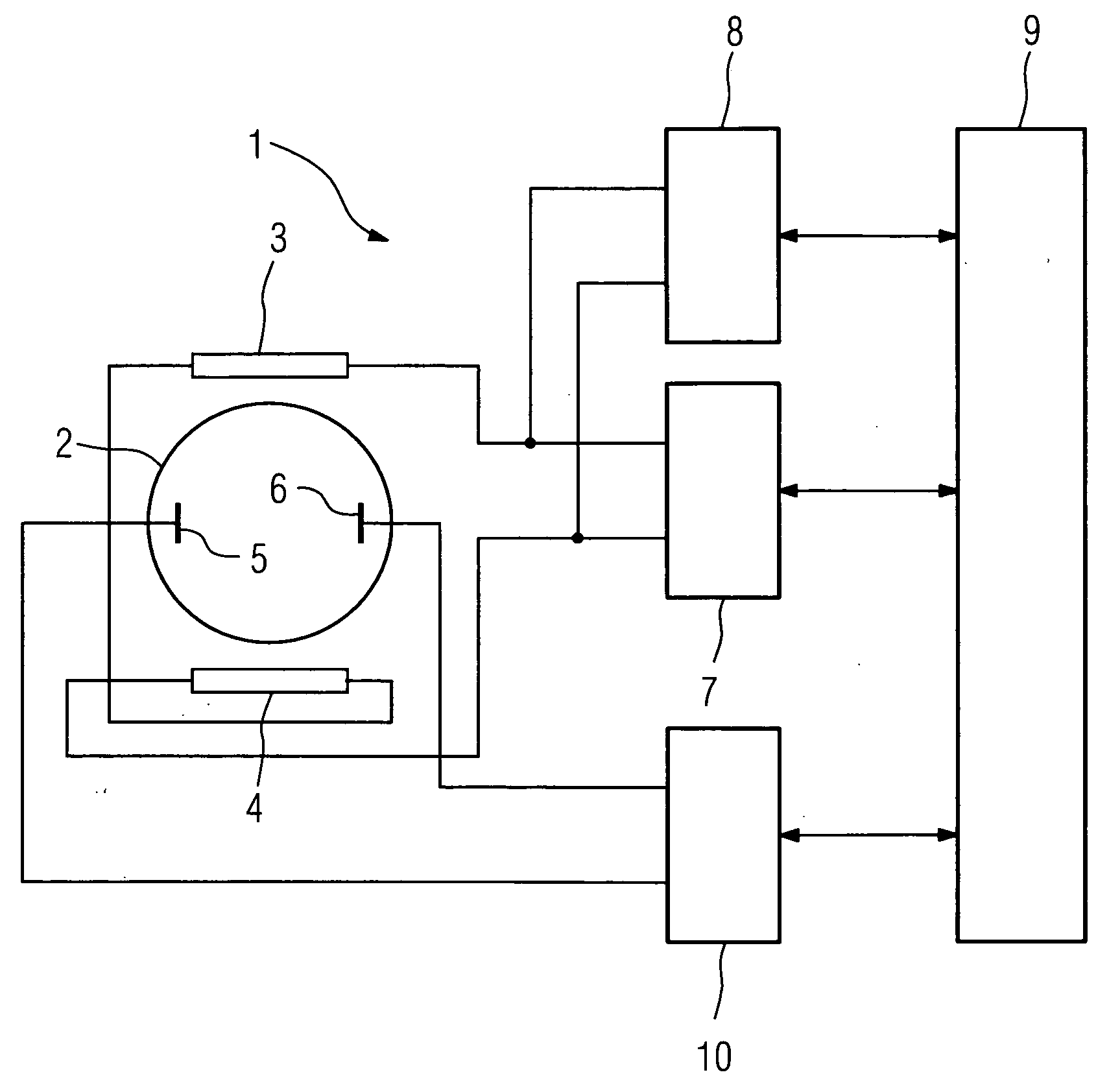
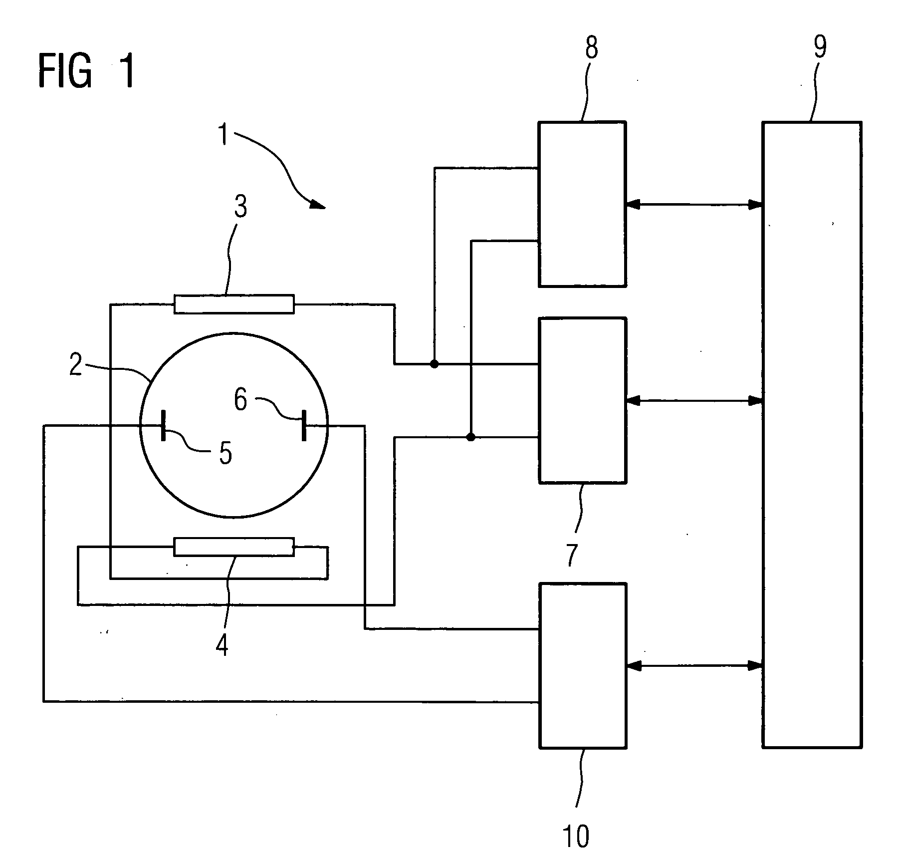
[0019]According to FIG. 1, an electromagnetic flowmeter 1 comprises a measuring tube 2 through which fluid flows perpendicularly to the drawing plane. The measuring tube 2 is electrically insulated. Arranged at the measuring tube 2 is a coil arrangement with two coils 3 and 4, which generate a magnetic field at right angles to the direction of flow when a current flows through the coils 3 and 4. Measuring electrodes 5 and 6 are provided in the measuring tube 2. These are arranged such that they detect a potential difference or voltage at right angles to the direction of flow and at right angles to the magnetic field. The voltage between the electrodes 5 and 6 is therefore proportional to the flow velocity of the medium flowing through the measuring tube 2 and to the strength of the magnetic field. The coils 3 and 4 are connected in series and are supplied, via a control device 7, with the voltage required for generating a magnetic field. Provided in the control device 7, in known ma...


PUM


Abstract

Disclosed is a method for operating an electromagnetic flowmeter and a flowmeter. A measuring tube provided with a coil arrangement for producing a magnetic field at right angles to the direction of flow. The direction of current flow in the coil arrangement is altered periodically, and the current is kept essentially constant in one period after a rise to a predetermined value. the voltage applied to the coil arrangement and/or its derivative is determined and compared with an associated reference value. If this voltage or derivative does not fall below the reference value in a desired minimum time within a measurement period, an error message can be emitted in order to indicate a fault. If the voltage or derivative falls below the reference value, it is ensured that the magnetic field is sufficiently stable and measured values for a voltage which can be tapped off at measurement electrodes.

Description

CROSS REFERENCE TO RELATED APPLICATIONS[0001]This application is the US National Stage of International Application No. PCT / EP2005 / 010224, filed Sep. 21, 2005 and claims the benefit thereof and is incorporated by reference herein in its entirety.FIELD OF INVENTION[0002]The invention relates to a method for operating an electromagnetic flowmeter according to the preamble of claim 1 and to an electromagnetic flowmeter according to claim 8 for carrying out the method.BACKGROUND OF THE INVENTION[0003]DE 199 17 268 A1 describes a method for testing an electromagnetic flowmeter and a flowmeter. The flowmeter has a measuring tube and a coil arrangement which generates a magnetic field at right angles to the direction of flow through the measuring tube, wherein the direction of the current flowing through the coil arrangement is periodically varied. In order to enable easy testing of the flowmeter, following a change in the direction of the current, at least one parameter of the current ris...

Claims


Application Information

Patent Timeline
IPC IPC(8): G01F1/58
CPCG01F25/0007G01F1/588G01F25/10
Inventor RASMUSSEN, CLAUS NYGAARD
Owner SIEMENS AG
Why Eureka
Try Eureka