Donor material technology for friction stir welding

a technology of friction stir welding and donor material, which is applied in the direction of manufacturing tools, soldering devices, auxillary welding devices, etc., can solve the problems of high tool wear, inconvenient use, and inability to meet the needs of heavy industries

Inactive Publication Date: 2009-10-22
OLD DOMINION UNIVERSITY RESEARCH FOUNDATION
View PDF19 Cites 19 Cited by
  • Summary
  • Abstract
  • Description
  • Claims
  • Application Information

AI Technical Summary

Benefits of technology

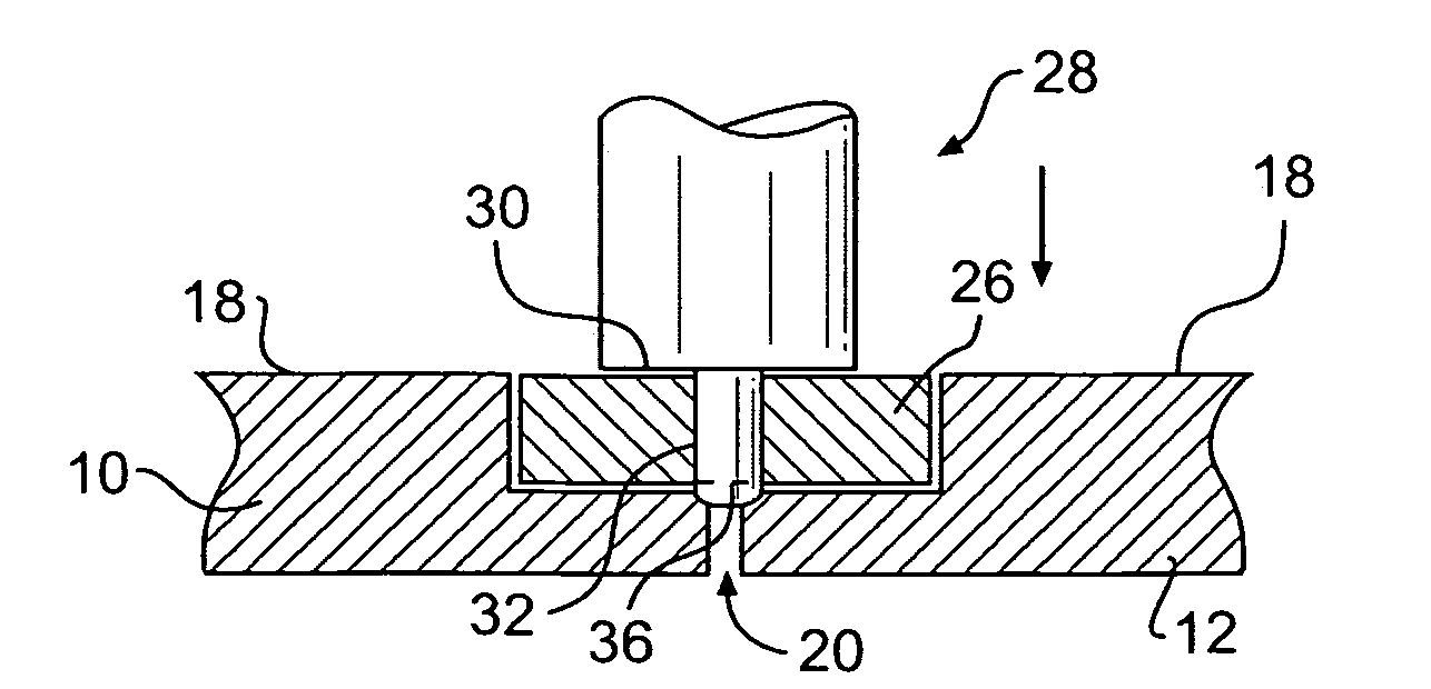
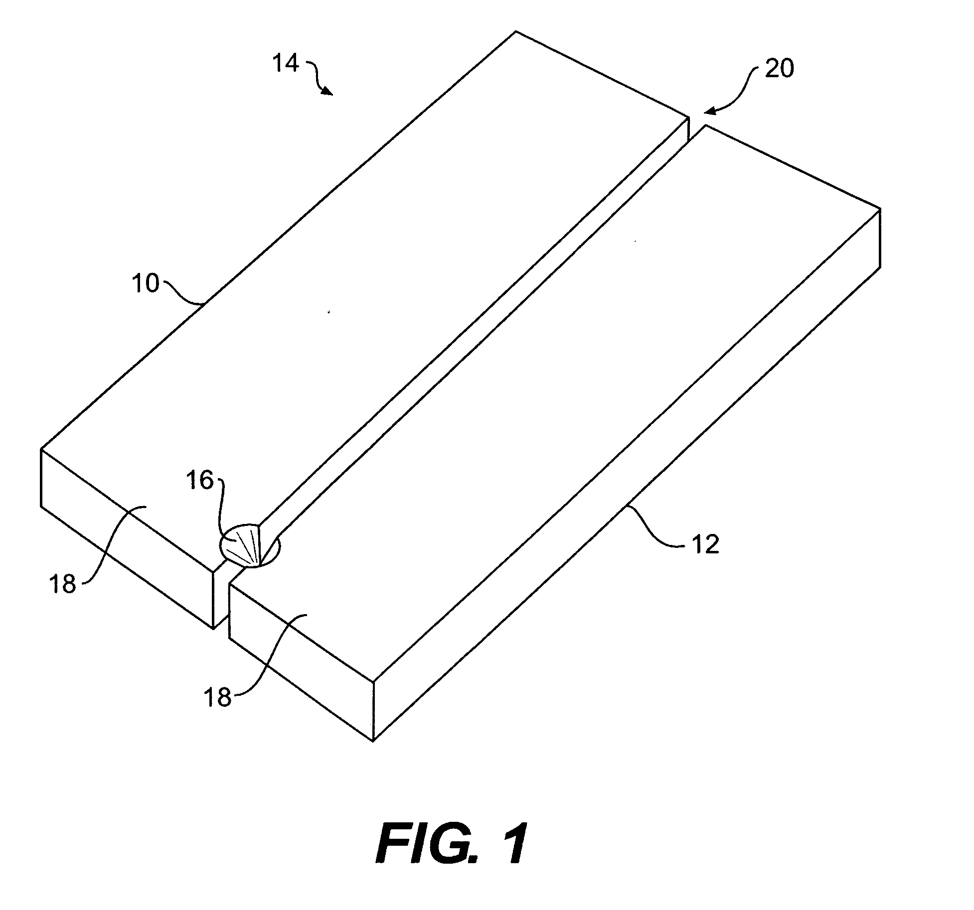
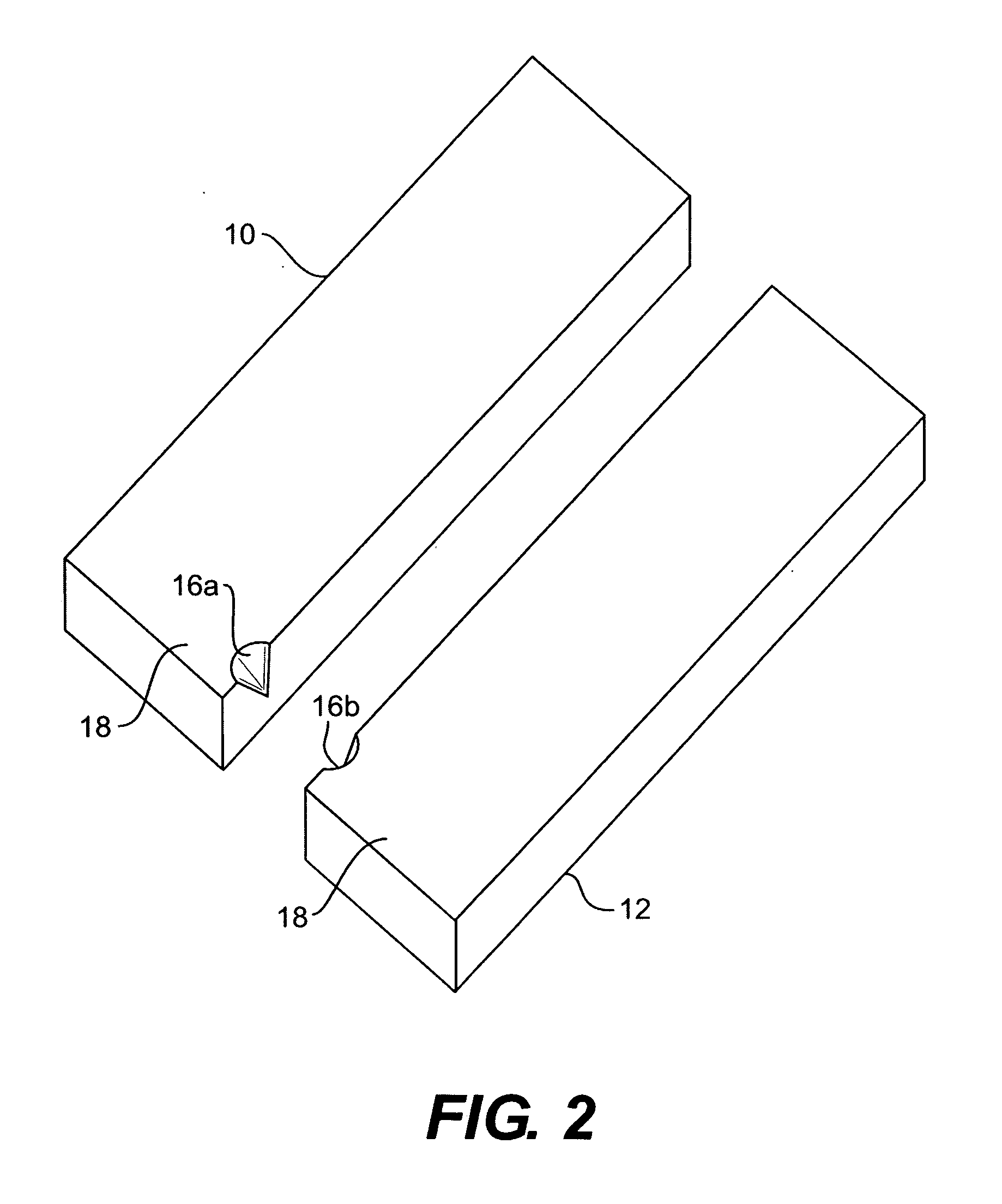
[0007]In one aspect of the present invention, a method for forming a friction stir weld joint using a friction stir tool includes providing a first metallic work material and a second metallic work material. The method also includes substantially abutting the first and second work materials to define a joint interface having a weld surface. A quantity of metallic donor material is provided and a depression having a shape is formed in the weld surface along the joint interface. The donor material is formed into a shape corresponding with the shape of the depression. The donor materia

Problems solved by technology

However, some disadvantages and limitations have been recognized in using FSW.
Although the process has been successfully used in some industries, it has not been popular in heavy industries, such as the shipbuilding industry.
The difficu

Method used


Image

  • Donor material technology for friction stir welding
  • Donor material technology for friction stir welding
  • Donor material technology for friction stir welding

Examples


example 1

[0046]Aluminum 1100 was used as the donor material inserted into the depression of a steel 1045 workpiece. A tool with 25.40 mm diameter shoulder and 6.35 mm diameter by 3.18 mm long tool pin was spun at 1,000 RPM and plunged into the donor material at a rate of 0.38 mm / s. Results were obtained by using the Computational Fluid Dynamics code software with non-Newtonian flow and low Reynolds number approximation. The flow around the tool pin during FSW is shown in FIGS. 6a and 6b.

[0047]Process simulation software was also used to simulate and analyze the three-dimensional flow of the FSW metal forming process. As shown in FIGS. 7 and 8, the temperature increased continuously during the plunge process until a maximum value greater than 477° C. was attained in the workpiece just below the shoulder. Most of the heat was generated by the work required for the deformation to punch the hole. As shown in FIGS. 7a and 7b, at time step 14,901, the tool pin was 89% of the way into the donor ma...

example 2

[0048]In the control test, a steel 1045 workpiece was friction stir welded without the use of a donor material. In the second test, a steel 1045 workpiece was friction stir welded with a donor material comprising Aluminum 2024. In the third test, a steel 1045 workpiece was friction stir welded with a donor material comprising Aluminum 6061. In the fourth test, a steel 1045 workpiece was friction stir welded with a donor material comprising copper.

[0049]The rotating tool was plunged into the 100 mm×100 mm×20 mm workpieces. The tool rotation speed was set at 300 RPM and the penetration speed was set at 4 mm / s. The simulation used commercial code and considered the plunge phase of the welding process. FIG. 8 shows a comparison of the interfacial shear stresses between the tool and the workpiece with and without the use of the donor materials during the plunge period. The interfacial shear stresses were much lower when using a combination of a donor material and steel as compared to a c...


PUM

PropertyMeasurementUnit
Forceaaaaaaaaaa
Diameteraaaaaaaaaa
Shapeaaaaaaaaaa

Abstract

A method and apparatus is disclosed for forming a friction stir weld joint using a friction stir tool. A first metallic work material and a second metallic work material are provided and are substantially abutted to define a joint interface having a weld surface. A quantity of metallic donor material is provided and deposited into a depression formed in the weld surface along the joint interface. A friction stir welding tool having a shoulder and a pin depending from the shoulder is provided and applied against the donor material within the depression using a plunge force. The friction stir welding tool is rotated such that the pin contacts the donor material and heats the donor material to plasticize at least a portion of the donor material forming a friction stir weld joint. The friction stir welding tool is then urged along the joint interface.

Description

CROSS-REFERENCE TO RELATED APPLICATION[0001]The present application claims priority benefit of U.S. Provisional Application No. 61 / 070,642, filed Mar. 25, 2008, which is herein incorporated by reference in its entirety.STATEMENT OF RIGHTS TO INVENTIONS MADE UNDER FEDERALLY SPONSORED RESEARCH AND DEVELOPMENT[0002]The U.S. Government has a paid-up license in this invention and the right in limited circumstances to require the patent owner to license others on reasonable terms as provided for by the terms of Grant No. 0343646 awarded by the National Science Foundation.BACKGROUND OF THE INVENTION[0003]Friction stir welding (FSW) is a solid-state welding process which allows work materials to be joined together. The FSW process involves a cylindrical, shouldered tool with a profiled pin which is rotated and plunged into a joint line between two pieces of material, which are abutted together. FSW generates heat by friction between the tool and the surrounding material, which thereby cause...

Claims


Application Information

Patent Timeline
IPC IPC(8): B23K20/12
CPCB23K20/122B23K20/124B23K2203/04B23K2201/18B23K20/128B23K2101/006B23K2101/18B23K2103/04
Inventor HOU, GENE J.WILLIAMSON, KEITH M.MANDAL, SAPTARSHIELMUSTAFA, ABDELMAGEED A.DEMUREN, AYODEJIBAWAB, SEBASTIAN Y.RICE, JUSTIN M.
Owner OLD DOMINION UNIVERSITY RESEARCH FOUNDATION
Why Eureka
Try Eureka