Optical probe

a technology of optical probes and probes, applied in the field of optical probes, can solve the problem that the resolution in the azimuthal direction cannot be enhanced, and achieve the effect of improving the resolution

Inactive Publication Date: 2009-10-22
TERUMO KK
View PDF4 Cites 50 Cited by
  • Summary
  • Abstract
  • Description
  • Claims
  • Application Information

AI Technical Summary

Benefits of technology

[0025]An optical probe disclosed here includes an optical probe which includes a drive shaft having an optical fiber driven to rotate in a sheath inserted in a body cavity, and an optical component attached to a distal portion of the optical fiber, and is operative to emit light, transmitted in the optical fiber, toward a living body tissue in the body cavity from the optical component. When the light transmitted in the optical fiber and emitted from the optical component is radiated to the living body tissue through the sheath, the optical component corrects the light on an optical path of the light so that a difference in coefficient of convergence or coefficient of divergence is generated between a drive axis direction of the drive shaft and an azimuthal direction around the drive axis direction of the drive shaft and that the difference between the diameter of the radiated light in the drive axis direction and the diameter of the radiated light in the azimuthal direction is thereby reduced. The optical probe disclosed here desirably enhances the resolution in the azimuthal direction of the cross-sectional image obtained.
[0026]The optical probe includes a drive shaft positionable in a sheath which is insertable in a body cavity, with the drive shaft being comprised of an optical fiber and an optical component attached to a distal portion of the optical fiber. The optical component comprises an inclined surface formed as a curved surface configured to reflect a light beam which has reached a distal portion of the optical fiber, and an outgoing surface formed as a convex surface facing outwards in an azimuthal direction around the drive axis direction, The inclined surface and the outgoing surface are configured to correct the light beam so that a difference in coefficient of convergence or coefficient of divergence is generated between the drive axis direction and the azimuthal direction and so that a difference between the diameter of the radiated light in the drive axis direction and the diameter of the radiated light in the azimuthal direction is thereby reduced.
[0027]According tom another aspect, an optical coherence tomography apparatus comprises a catheter device comprised of a drive shaft, a scanner and pull-back unit operatively connected to the catheter device to effect radial scanning of the drive shaft, and a controller operatively connected to the scanner and pull-back unit to control operation of the scanner and pull-back unit. The drive shaft includes an optical fiber rotatably positioned in a sheath configured to be inserted in a body cavity, and an optical component attached to the distal portion of the optical fiber and operative to emit light, transmitted in the optical fiber, through the sheath as radiated light directed toward living body tissue in the body cavity, Additionally, the optical component comprises means for correcting the light, which is transmitted in the optical fiber on an optical path, so that a difference in coefficient of convergence or coefficient of divergence is generated between a drive axis direction of the drive shaft and an azimuthal direction around the drive axis direction and so that a difference between the diameter of the radiated light in the drive axis direction and the diameter of the radiated light in the azimuthal direction is thereby reduced.

Problems solved by technology

However, in the case where the light beam has been undesirably spread in the azimuthal direction due to the above-mentioned concave lens effect of the sheath, no matter how much the number of scan lines is increased, the resolution in the azimuthal direction cannot be enhanced.

Method used


Image

  • Optical probe
  • Optical probe
  • Optical probe

Examples


first embodiment

1. Configuration of Optical Coherence Tomography Apparatus

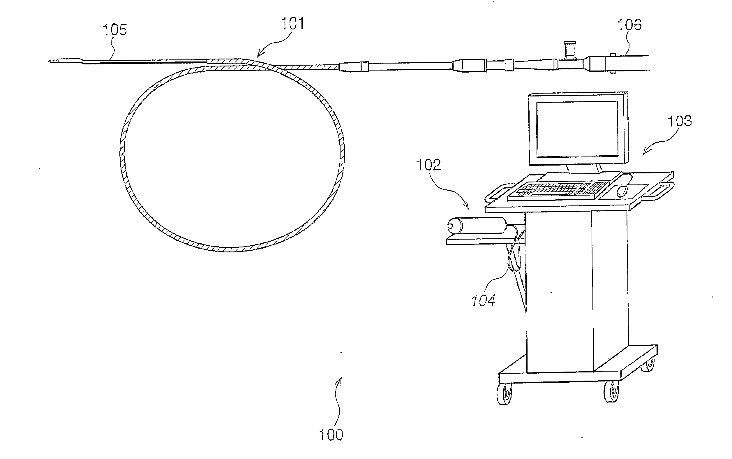
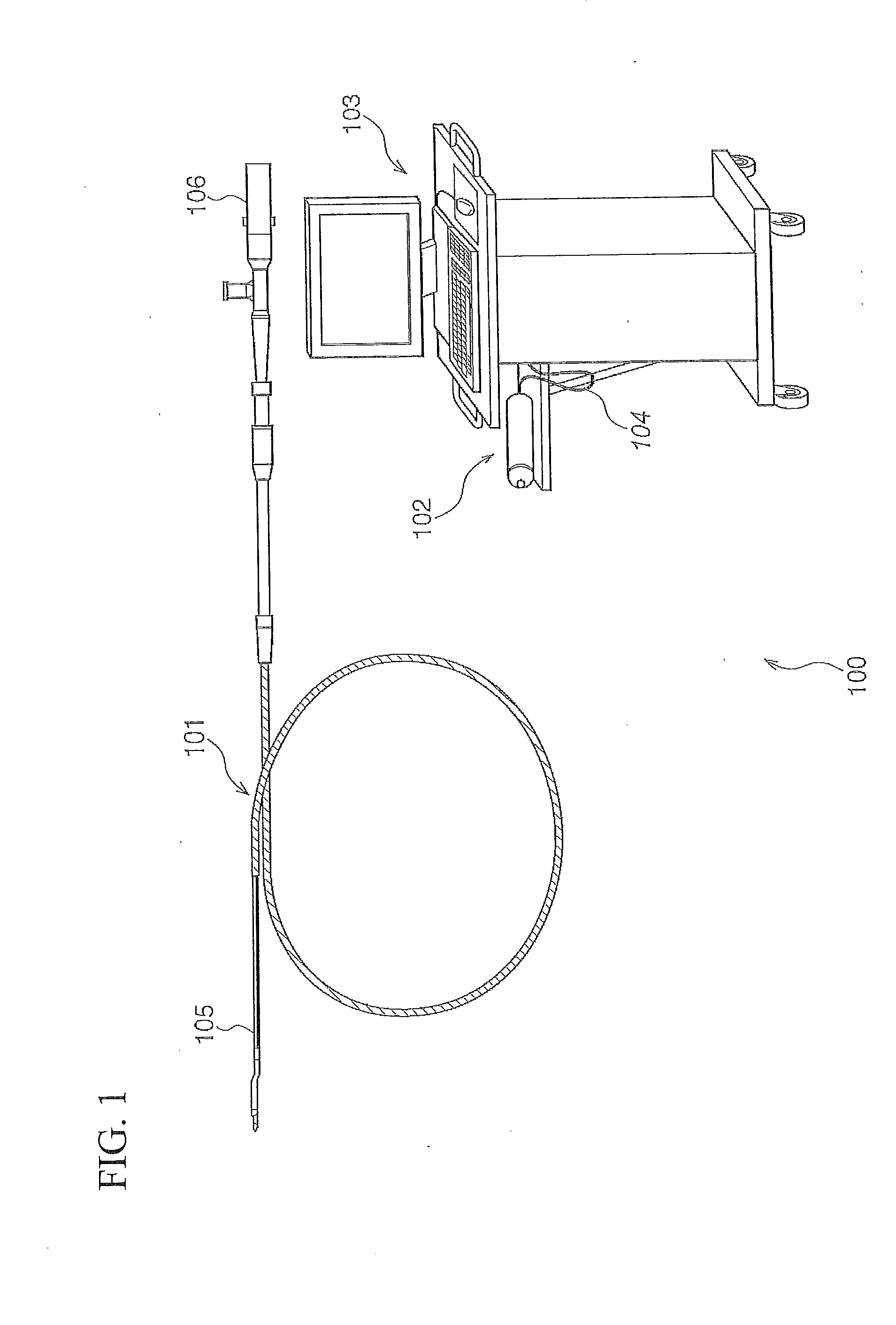
[0066]FIG. 1 illustrates the overall appearance and configuration of an optical coherence tomography apparatus 100 disclosed here including a catheter device according to a first embodiment disclosed here.

[0067]As shown in FIG. 1, the optical coherence tomography apparatus 100 includes a catheter device 101, a scanner and pull-pack unit or section 102, and an operation controller 103. The scanner and pull-back section 102 and the operation controller 103 are connected to each other by a signal cable 104.

[0068]The catheter device 101 is inserted directly into a blood vessel, and measures the condition in the blood vessel by use of reflected light of coherent light emitted via an optical component. The scanner and pull-back section 102 is connected to a connector 106 of the catheter device 101, and effects radial scanning of a drive shaft 105 inside the catheter device 101.

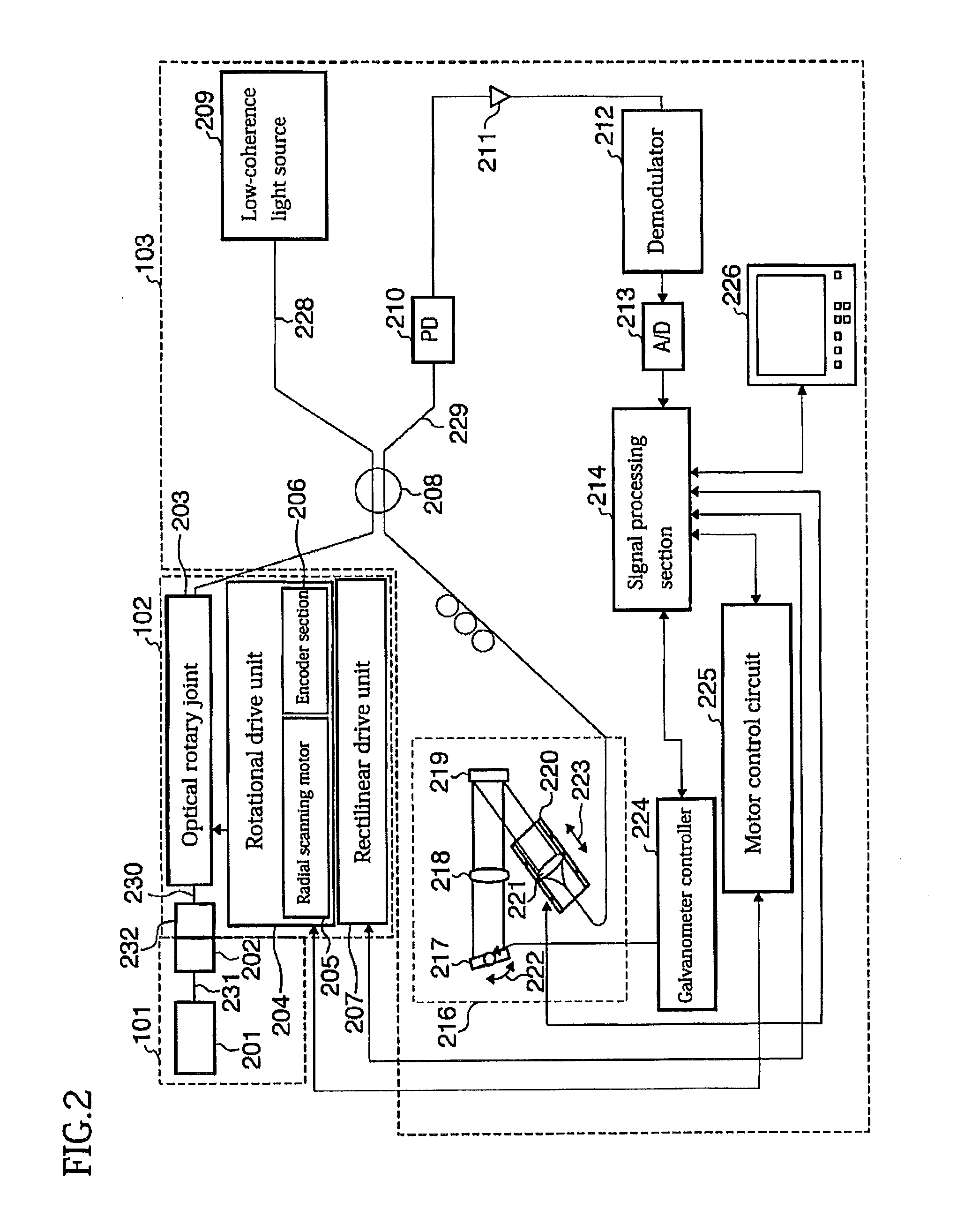
[0069]The operation controller 103 is configured to per...

second embodiment

[0122]The reflecting surface 601 of the prism 308 in the first optical component 305 is a convex surface facing outwards in the azimuthal direction in order to cancel the concave lens effect of the catheter sheath 301 in the above-described first embodiment. However, the disclosure here is not particularly limited to or by this configuration. For example, an outgoing surface of the prism 308 may be formed as a convex surface facing outwards in the azimuthal direction.

[0123]FIGS. 11-13 illustrate parts of a first optical component 1100 of a catheter device according to this embodiment.

[0124]As shown in FIGS. 11-13, in the first optical component 1100, a prism (deflector) 1101 includes a reflecting or deflecting surface 1102 for a light beam that is a flat surface, whereas an outgoing surface 1103 for the light beam is formed as a convex surface facing outwards in the azimuthal direction. The outgoing surface 1103 of the prism refers to the surface of the prism through which the light...

third embodiment

[0134]The catheter device including the first optical component has been described above in connection with the first and second embodiments, though the device is not limited in this respect. In a catheter device including a second optical component, similarly the resolution in the azimuthal direction of the cross-sectional image can be enhanced.

1. General Configuration of Second Optical Component and Light Beam Ray Trajectories

[0135]A general configuration of the second optical component in the catheter device according to this embodiment and the ray trajectories in the process up to the emission of a light beam through the second optical component are described below.

1.1 General Configuration of Second Optical Component

[0136]FIG. 15 illustrates as a cross-sectional view in a sideways direction a distal part of a drive shaft 105 at a distal portion of the catheter device 101. FIG. 15 shows that the distal portion of the catheter device 101 has a configuration in which the drive sha...


PUM


Abstract

A catheter device for an optical coherence tomography apparatus is configured to enhance the resolution of the cross-sectional image in the azimuthal direction. The catheter device includes a drive shaft driven to rotate in a catheter sheath, an optical fiber in the drive shaft and driven to rotate with the drive shaft, and an optical component attached to a distal portion of the optical fiber. The catheter device emits light, transmitted in the optical fiber, into a body cavity through the optical component. A surface on the optical path of the optical component is a curved surface facing the drive shaft direction or the azimuthal direction to ensure that, when light emitted from the optical component is radiated into the body cavity via the catheter sheath, the difference between the diameter of the radiated light in the drive axis direction and the azimuthal direction is reduced.

Description

[0001]This application is a continuation of International Application No. PCT / JP2007 / 072194 filed on Nov. 15, 2007, the entire content of which is incorporated herein by reference. This application is also based on and claims priority to Japanese Application No. 2006-356019 filed on Dec. 28, 2006, the entire content of which is incorporated herein by reference.TECHNICAL FIELD[0002]The present invention generally relates to an optical probe. More specifically, the present invention pertains to an optical probe having useful application in an optical coherence tomography apparatus.BACKGROUND ART[0003]Catheter type imaging diagnostic apparatuses have been used for diagnosis of arteriosclerosis, for pre-operation diagnosis in the case of intravascular treatment by use of a high-functional catheter such as a balloon catheter, a stent, etc. or for post-operation confirmation of the results of an operation.[0004]An example of an imaging diagnostic apparatus is an intravascular ultrasound (...

Claims


Application Information

Patent Timeline
Patent Type & Authority Applications(United States)
IPC IPC(8): G01B11/24G01B9/02
CPCA61B5/0066A61B5/6852A61B2017/00057G01N2021/4742A61B2017/22001G01N21/4795A61B2017/00061G02B6/0008G02B6/262
Inventor TANIOKA, HIROMICHITAKAHASHI, KAZUYUKI
Owner TERUMO KK
Why Eureka
Try Eureka