Method for characterizing a geological formation traversed by a borehole

Inactive Publication Date: 2009-10-22
SCHLUMBERGER TECH CORP
View PDF92 Cites 69 Cited by
  • Summary
  • Abstract
  • Description
  • Claims
  • Application Information

AI Technical Summary

Benefits of technology

[0023]The FILTERSIM algorithm starts with a classification of local training patterns in a filter score space of reduced dimension. Simulation proceeds along a sequential path through the simulation space, by determining which pattern class is most similar to the local conditioning data event, sampling a specific pattern from the pattern class, and then patching the sampled pattern onto the

Problems solved by technology

At very small scales (less than 6 in; 15 cm), nonlinear depth shifts occur that may not be correctable by conventional data-processing algorithms.
High mud resistivities (greater than 50 ohm-m), typical of oil-based muds, are unsuitable for most electrical borehole images.
However, poor-quality images may result when the tool is decentralized, or the borehole wall is irregular.
Therefore, as discussed above, because electrical logging tools are pad-type devices with fixed arrays of electrodes, it is common to have gaps with missing information between the pads.
Electrical and acoustic logs commonly have intervals with poor data quality due to non-functioning electrodes, insufficient pad pressure, borehole irregularities, rock debris, decentralized tools, and poor acoustic reflections.
One of the limitations of the first MPS approach, however, was that it was extremely computationally intensive to consult the training image multiple times. In 2000, Strebelle developed a technique to store the information contained in the training image in a special tree-like structure that reduced computations enormously (Strebelle, S., 2000, Sequential simulation dra

Method used


Image

  • Method for characterizing a geological formation traversed by a borehole
  • Method for characterizing a geological formation traversed by a borehole
  • Method for characterizing a geological formation traversed by a borehole

Examples


Example

[0059]It will be recognized by the person of ordinary skill in the art, given the benefit of this disclosure, that certain dimensions, features, components, and the like in the figures may have been enlarged, distorted or otherwise shown in a non-proportional or non-conventional manner to facilitate a better understanding of the technology disclosed herein.

DETAILED DESCRIPTION OF THE INVENTION

[0060]The following description provides exemplary embodiments only, and is not intended to limit the scope, applicability, or configuration of the disclosure. Rather, the following description of the exemplary embodiments will provide those skilled in the art with an enabling description for implementing one or more exemplary embodiments. It being understood that various changes may be made in the function and arrangement of elements without departing from the spirit and scope of the invention as set forth in the appended claims.

[0061]Specific details are given in the following description to ...


PUM


Abstract

Methods for characterizing a geological formation, the methods include retrieving measured data provided by a measuring tool along one or more logged borehole length for a borehole, another borehole or both in order to produce a borehole imaging log. Selecting depth-defined intervals of the borehole imaging log as training images for inputting in a multi-point geostatistical model. Determining pattern based simulations for each training image using a pixel-based template of the multi-point geostatistical model so as to obtain training image patterns. Using the pattern based simulation of each training image to assign to each of the training image a corresponding training image pattern. Constructing from the training image patterns one or more fullbore image log of a borehole wall of the borehole. Repeat the second to fourth steps through the one or more logged borehole length in order to construct fullbore images from successive, adjacent training images.

Description

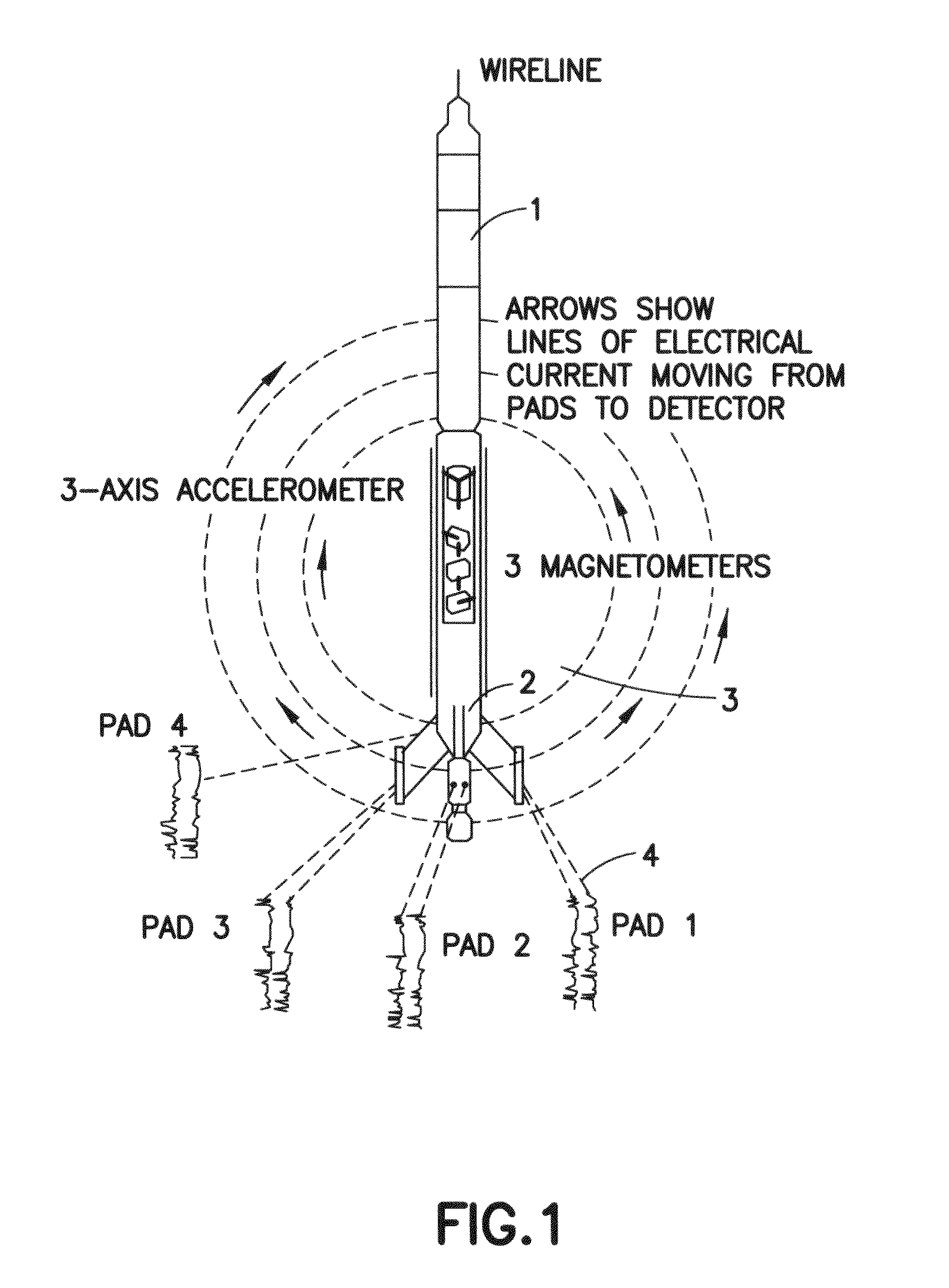
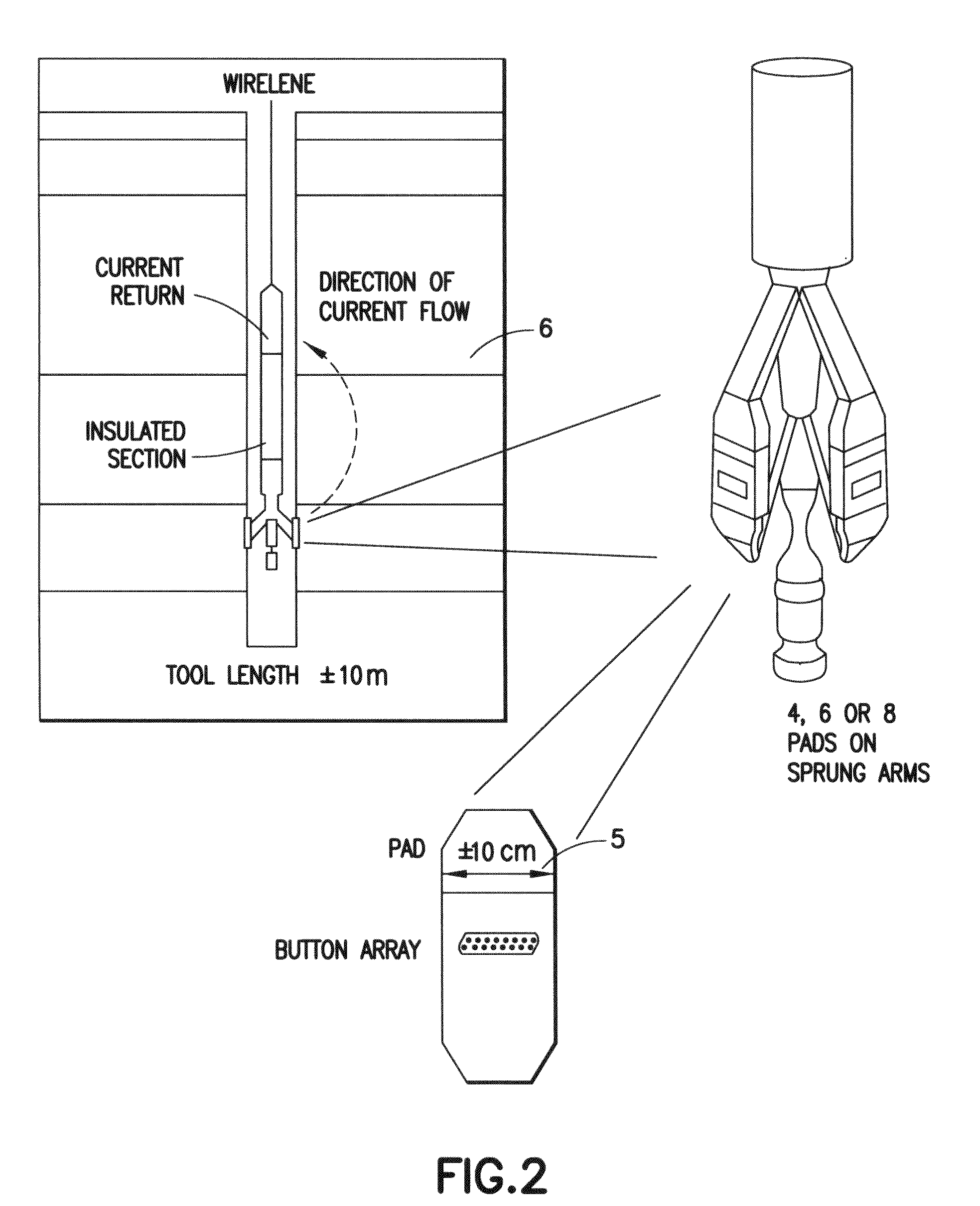
FIELD OF THE INVENTION[0001]This invention relates broadly to the investigation of geological formations traversed by a borehole. More particularly, this invention relates to a method for characterizing a geological formation providing 360-degree views of the borehole wall.BACKGROUND OF THE INVENTION[0002]Electrical and acoustic borehole-imaging tools are widely used to log subsurface boreholes to locate and map the boundaries between rock layers (i.e., bed boundaries), and to visualize and orient fractures and faults[0003]Electrical borehole images run in water-based mud, such as Schlumberger's FMI (Formation MicroImager) log, are based on dipmeter technology that has been commercially available since the 1950's (Bigelow, 1985a, b, c, d, e; Gilreath, 1987; Adams et al., 1987; Hurley, 2004). FIG. 1 is an illustration of the tool configuration and basic principles behind dipmeter logs. Electrical borehole-imaging tools are, in essence, sophisticated dipmeters. The imaging tools have ...

Claims


Application Information

Patent Timeline
IPC IPC(8): G01V1/00G06T15/00G06F19/00
CPCG01V11/00G01V2210/665
Inventor HURLEY, NEIL FRANCISZHANG, TUANFENG
Owner SCHLUMBERGER TECH CORP
Why Eureka
Try Eureka