Tunable optical filter

a technology of optical filters and tunable filters, applied in the field of tunable optical filters, can solve the problems of reducing the size and cost of the device, affecting the measurement of signal level, and the optical filter of henry et al. is not tunable, so as to reduce the size of the plc chip

Active Publication Date: 2009-10-22
LUMENTUM OPERATIONS LLC
View PDF12 Cites 25 Cited by
  • Summary
  • Abstract
  • Description
  • Claims
  • Application Information

AI Technical Summary

Benefits of technology

[0013]According to one aspect of the present invention, the tunable MZ interferometers of the tunable filter are comprised of planar waveguides of a planar lightwave circuit (PLC) chip that is small enough to be placed within said hot-pluggable XFP transceiver package. The size reduction of the PLC chip is achieved by using a length of an optical fiber that is placed to loop back from one side of the PLC chip to another side, thereby removing a necessity to accommodate waveguide turns on the PLC chip. Alternatively, according to another aspect of the present invention, the size of the PLC chip is reduced by using a mirror attached to an edge of the chip, either for double passing through at least a portion of the PLC chip, or for reflecting at an angle from one end waveguide of the PLC chip to another end waveguide, wherein the two end waveguides form a V-shape, with a mirror being disposed at the tip of the V-shape, so as to optically couple the two said end waveguides together.

Problems solved by technology

A poor crosstalk suppression leads to undesired “leaking” of the optical channels being suppressed, which impairs the signal level measurements and / or detection and decoding of the selected signal.
Detrimentally, the optical filter of Henry et al. is not tunable.
Detrimentally, it also requires many components such as blocking tunable filters, 1×N splitters, switches, and interleavers, which complicates the device and increases its size and cost.

Method used


Image

  • Tunable optical filter
  • Tunable optical filter
  • Tunable optical filter

Examples


Embodiment Construction

[0042]While the present teachings are described in conjunction with various embodiments and examples, it is not intended that the present teachings be limited to such embodiments. On the contrary, the present teachings encompass various alternatives, modifications and equivalents, as will be appreciated by those of skill in the art.

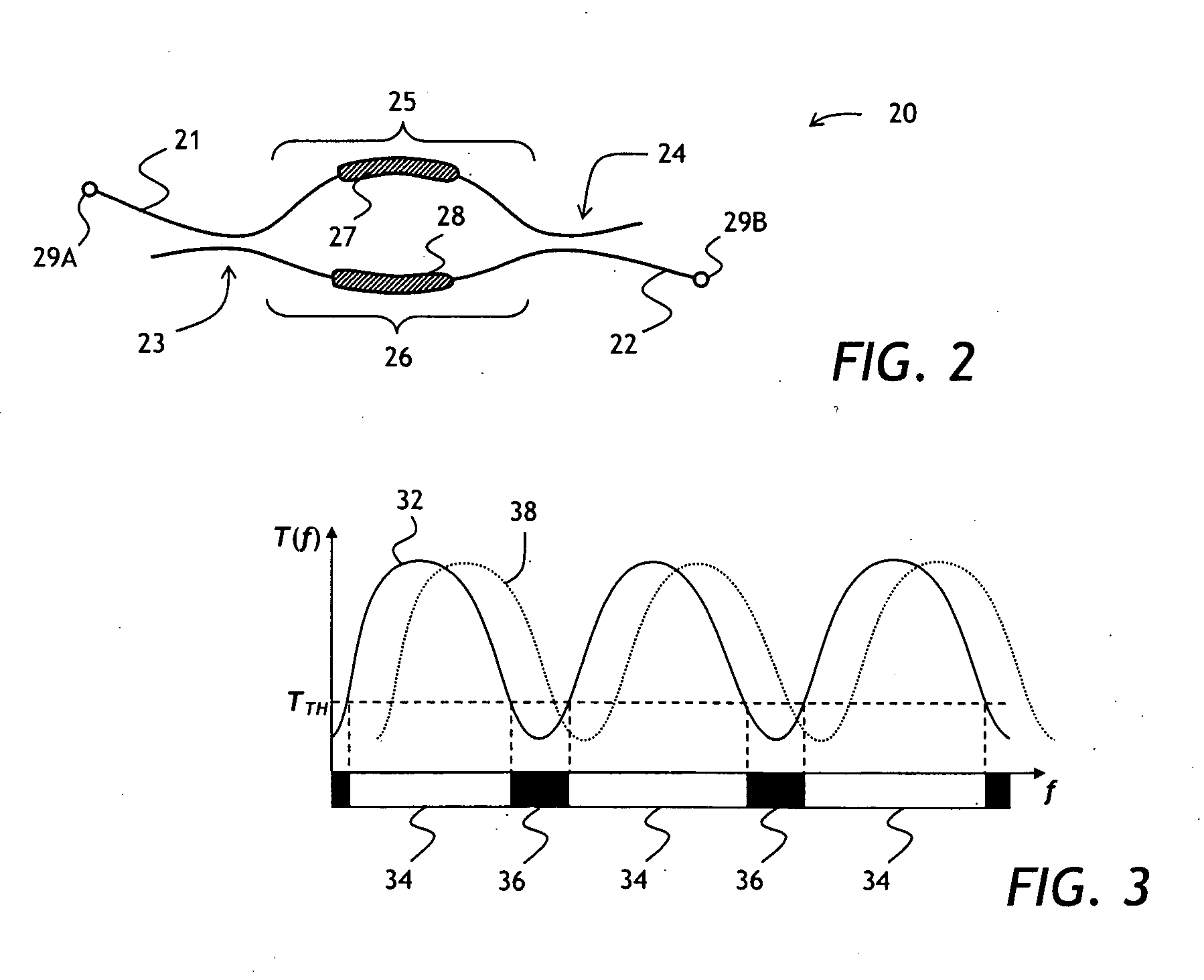
[0043]Referring to FIG. 2, an optical diagram of an unbalanced MZ interferometer 20 used in the present invention is shown. The MZ interferometer 20 has two waveguides 21 and 22 brought into close proximity to each other at 50%, or 3-dB, evanescent coupler regions 23 and 24, thereby forming two arms 25 and 26. The arms 25 and 26 have a localized heater 27 and 28, respectively, for heating the arms 25 and 26 thereby tuning the MZ interferometer 20 by changing relative optical length of these arms. The MZ interferometer 20 is an unbalanced MZ interferometer, meaning that the optical lengths of the arms 25 and 26 differ from each other by more than a few mic...


PUM


Abstract

A tunable PLC optical filter having sequentially connected thermally tunable Mach-Zehnder (MZ) interferometers is described. The MZ interferometers, having free spectral ranges matching ITU frequency grid spacing, are tuned so as to have a common passband centered on the frequency of the signal being selected, while having at least one of the stopbands centered on any other ITU frequency. Any other optical channel that may be present at any other ITU frequency is suppressed as a result. The PLC chip, including a zero-dispersion lattice-filter interleaver stage, a switchable fine-resolution stage and, or a retroreflector for double passing the filter, is packaged into a hot-pluggable XFP transceiver package. A compensation heater is used to keep constant the amount of heat applied to the PLC chip inside the XFP package, so as to lessen temperature variations upon tuning of the PLC optical filter.

Description

CROSS-REFERENCE TO RELATED APPLICATIONS[0001]The present invention claims priority from U.S. Patent Application No. 61 / 029,987 filed Feb. 20, 2008, which is incorporated herein by reference for all purposes.TECHNICAL FIELD[0002]The present invention relates to a tunable optical filter, and in particular to a tunable optical filter having cascaded Mach-Zehnder interferometers.BACKGROUND OF THE INVENTION[0003]Optical filters are devices for selecting at least one optical frequency band, called a passband, out of an optical frequency spectrum of an optical signal. A central frequency of the passband of a tunable optical filter is adjustable, depending upon a control parameter common to a particular filter type. For example, for a bulk optic tunable filter, the control parameter can be a filter tilt or a clocking (rotation) angle with respect to an incoming optical beam. For an optical waveguide based tunable filter such as tunable Mach-Zehnder (MZ) interferometer, the control parameter...

Claims


Application Information

Patent Timeline
Patent Type & Authority Applications(United States)
IPC IPC(8): H04B10/00
CPCG02B6/12007G02B6/4201G02F2203/055G02F2201/16G02F1/225
Inventor SHEN, JINXIBHARDWAJ, JYOTI K.FONDEUR, BARTHELEMYCRAFTS, DOUGLAS E.BRAINARD, ROBERT J.XIE, BOPINGCHAPMAN, DAVID J.
Owner LUMENTUM OPERATIONS LLC
Why Eureka
Try Eureka