Compressor Unit

a compressor unit and compressor technology, applied in the direction of positive displacement liquid engines, piston pumps, liquid fuel engines, etc., can solve the problems of introduction of heat into the pump flow, and it is virtually impossible to use seawater as a cooling medium, so as to reduce the complexity of cooling and improve the interaction

Inactive Publication Date: 2009-10-22
SIEMENS AG
View PDF3 Cites 22 Cited by
  • Summary
  • Abstract
  • Description
  • Claims
  • Application Information

AI Technical Summary

Benefits of technology

[0009]Against the background of the problems of the prior art, the object of the invention is to provide a better interaction between the automation

Problems solved by technology

It is virtually impossible to use seawater as a cooling medium, because of the aggressive chemical ch

Method used


Image

  • Compressor Unit
  • Compressor Unit

Examples


Embodiment Construction

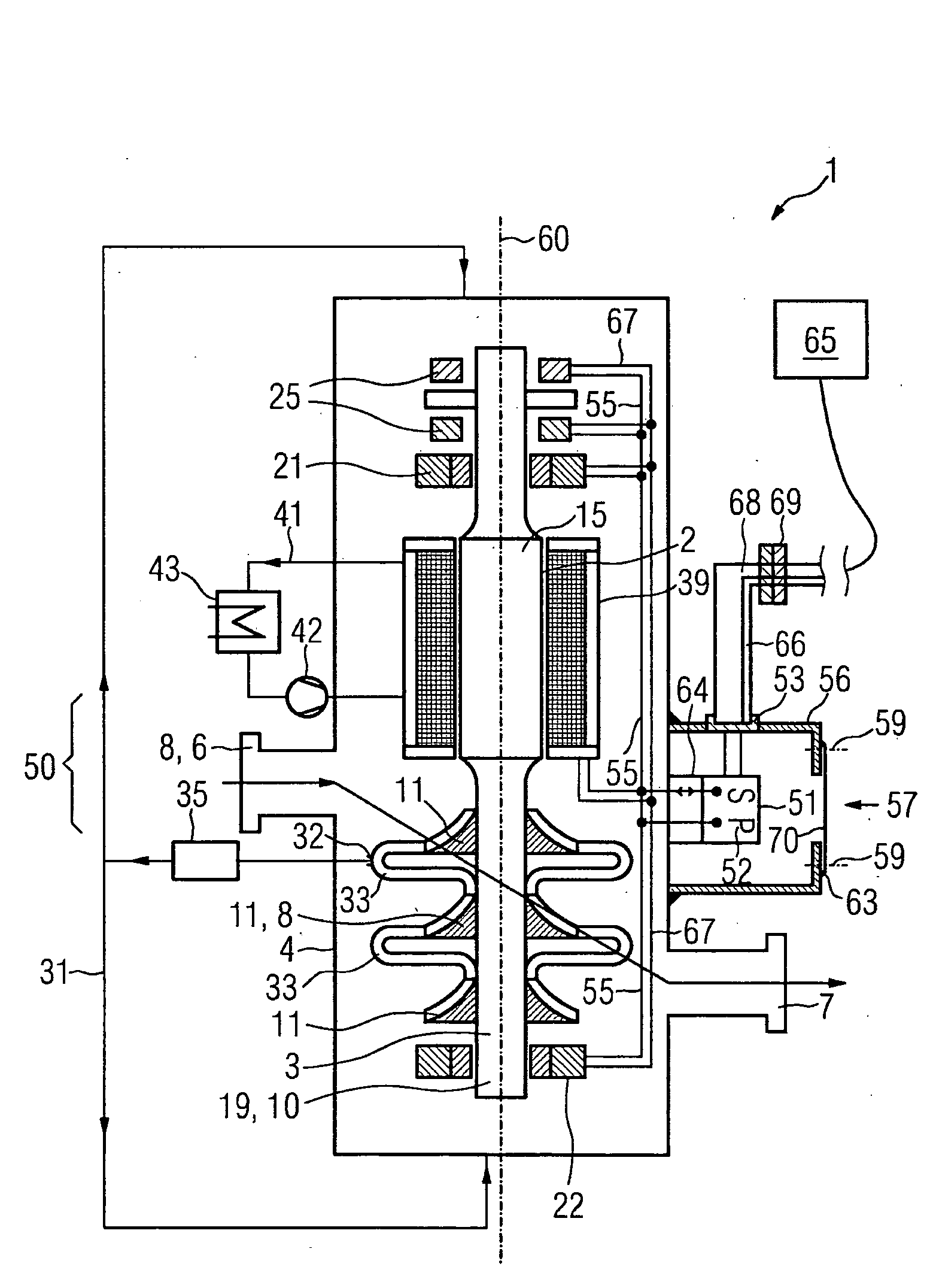
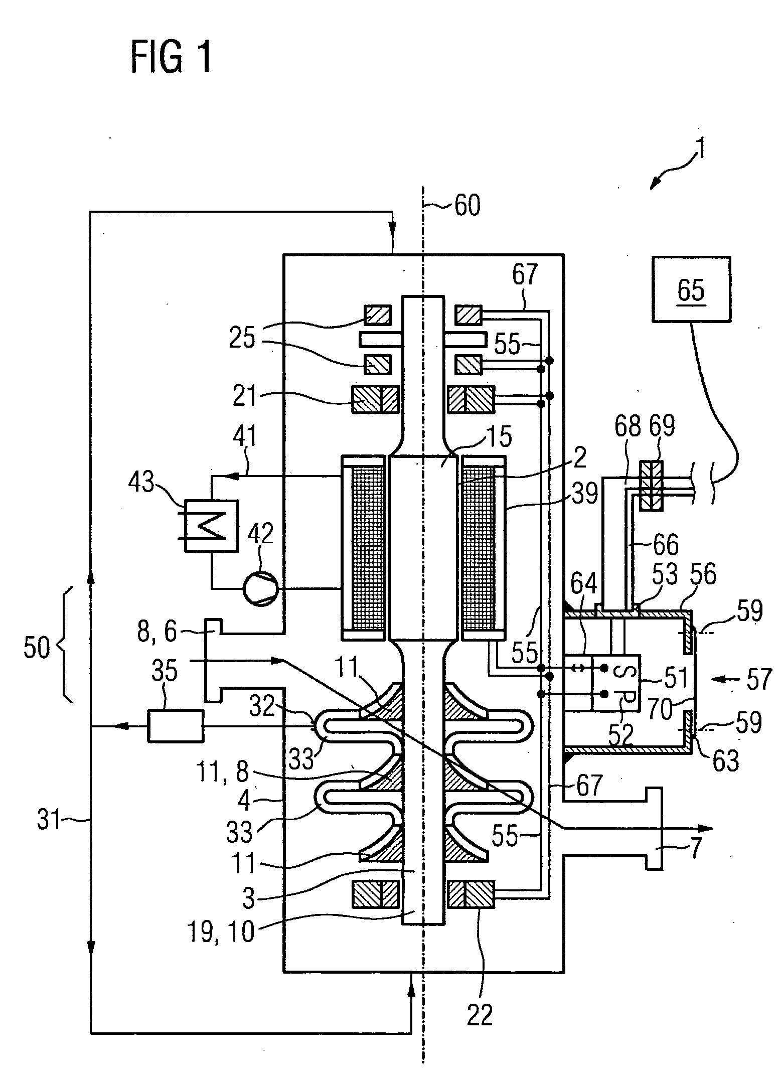
[0019]FIG. 1 shows a section along a compressor unit 1 according to the invention which has, as major components, a motor 2 and a compressor 3 in a housing 4 which is designed to be gas-tight. The housing 4 accommodates the motor 2 and the compressor 3. In the area of the junction between the motor 2 and the compressor 3, the housing 4 is provided with an inlet 6 and an outlet 7, with the fluid to be compressed being sucked in through the inlet 6 by means of an intake connecting stub 8, and with the compressed fluid flowing out through the outlet 7.

[0020]The compressor unit 1 is arranged vertically during operation, with a motor rotor 15 of the motor 2 being combined via a compressor rotor 9 of the compressor 3 to form a common shaft 19, which rotates about a common vertical rotation axis 60.

[0021]The motor rotor 15 is mounted in a first radial bearing 21 at the upper end of the motor rotor 15.

[0022]The compressor rotor 9 is mounted in a second radial bearing 22 at a lower position....


PUM


Abstract

The invention relates to a compressor unit, in particular for underwater operations, comprising a compressor with a rotational axis and an electric motor. Said compressor unit has a housing with an automation unit for control and regulation tasks. The aim of the invention is to improve the co-operation of the automation unit and the compressor unit and in particular to reduce the complexity of the cooling of the automation unit and signal and energy transmission. To achieve this, an additional housing, which contains the automation unit, is attached to the housing.

Description

CROSS REFERENCE TO RELATED APPLICATIONS[0001]This application is the US National Stage of International Application No. PCT / EP2007 / 051474, filed Feb. 15, 2007 and claims the benefit thereof. The International Application claims the benefits of European application No. 06006059.7 filed Mar. 24, 2006, both of the applications are incorporated by reference herein in their entirety.FIELD OF INVENTION[0002]The invention relates to a compressor unit, in particular for underwater operation, comprising a compressor with a rotation axis and an electric motor, which compressor unit has a housing which has an inlet and an outlet for a pumping medium, having an automation unit which is designed such that it carries out open-loop and closed-loop control tasks for the compressor unit.BACKGROUND OF THE INVENTION[0003]Recent developments in the field of compressor design have also been concentrated on undersea arrangements of large compressors which are intended to be used for the pumping of natura...

Claims


Application Information

Patent Timeline
IPC IPC(8): F01C21/00F04B17/03
CPCF04D17/122F04D27/00F04D27/0261F04D29/4206F04D25/0686H02K5/132H02K5/225H02K7/14H02K11/0073F04D29/584F04D29/5813F04D29/5853H02K11/33
Inventor MATHIJSSEN, GASTONVAN AARSEN, MARK
Owner SIEMENS AG
Why Eureka
Try Eureka