Process and Plant for Substitute Natural Gas

Active Publication Date: 2009-10-22
CASALE SA
View PDF1 Cites 27 Cited by
  • Summary
  • Abstract
  • Description
  • Claims
  • Application Information

AI Technical Summary

Benefits of technology

[0026]All the above advantages make the SNG more competitive over fossil natural gas or other

Problems solved by technology

As a consequence, the power absorption of the compressor for gas recirculation is quite high and hence the compressor itself is a large and expensive item.
Another drawback is that

Method used


Image

  • Process and Plant for Substitute Natural Gas
  • Process and Plant for Substitute Natural Gas

Examples


Example

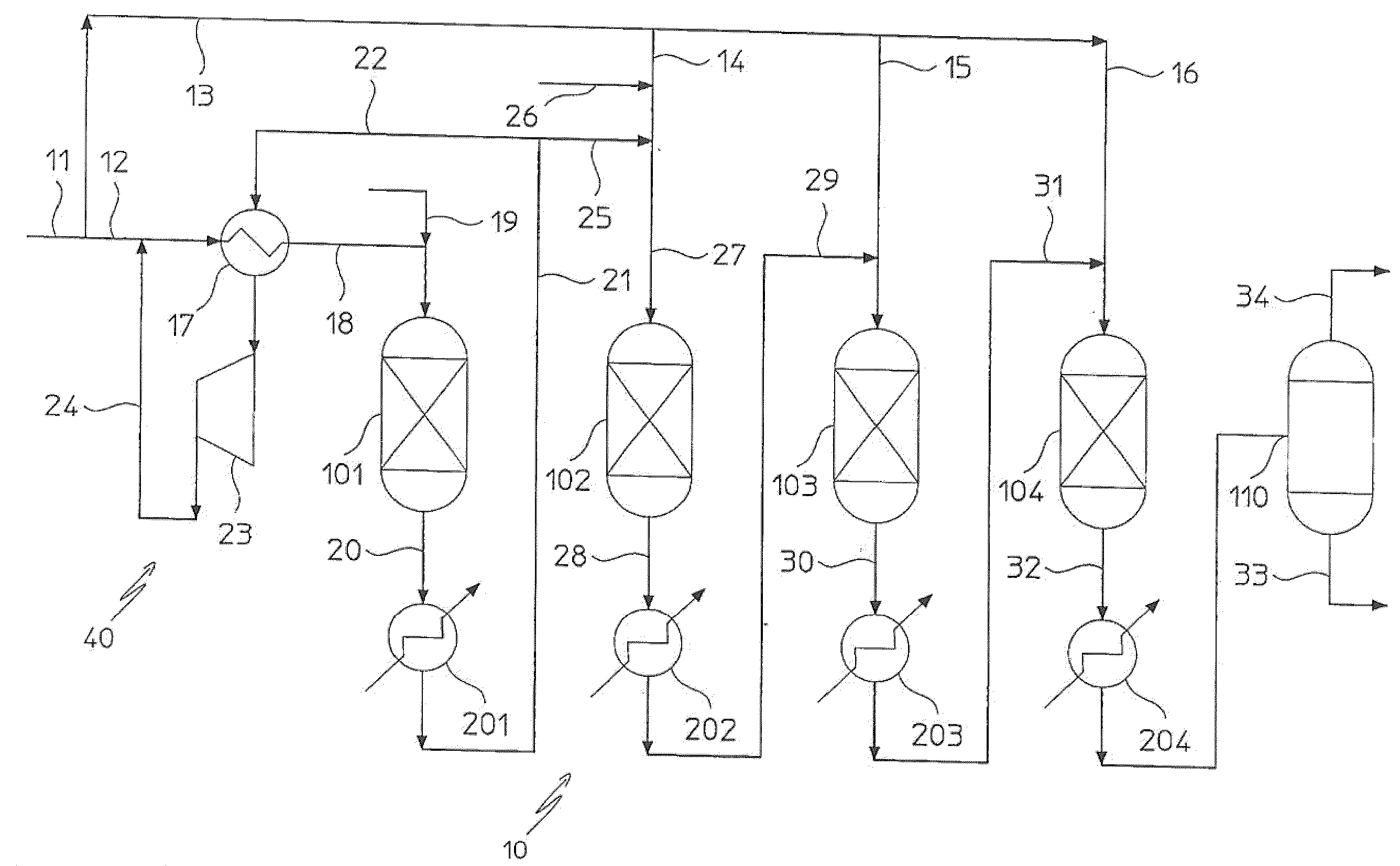
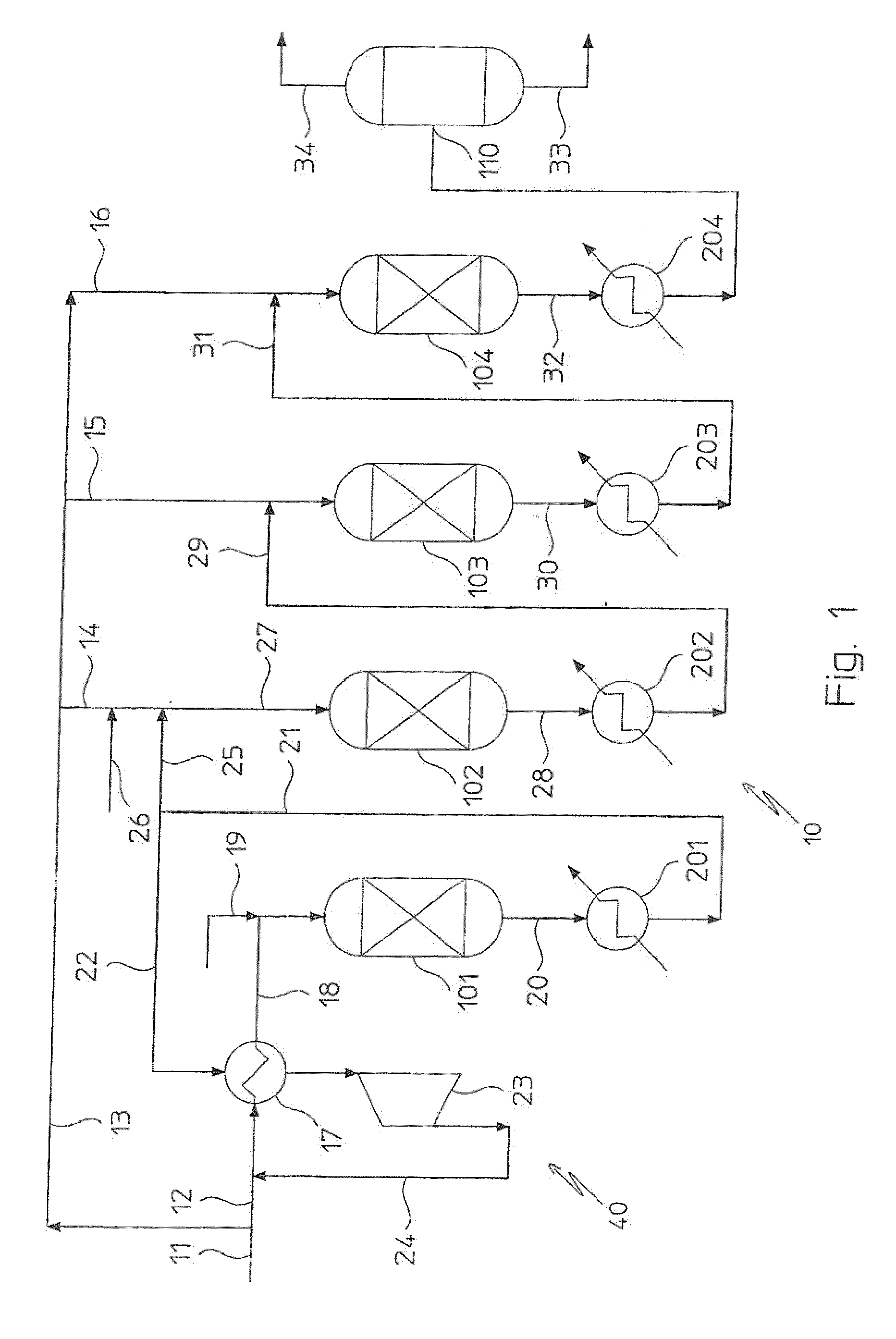
[0029]With reference to FIG. 1, a methanation section for SNG production is globally indicated as 10, and receives a feedstock 11 of a fresh syngas containing carbon oxides and hydrogen. Said fresh syngas stream 11 can be obtained for example in a coal or biomass gasification section (not shown).

[0030]The methanation section 10 comprises a series of adiabatic reactors 101-104 with recovery heat exchangers 201-204. Reactors 101 to 104 are per se known, for example axial or axial-radial flow reactors with an appropriate catalyst, operating at around 35 bar pressure with inlet gas temperature between 240 and 300° C. and outlet gas temperature around 600° C. Heat exchangers 201 to 204 receive the hot gas from reactors 101 to 104, respectively, and may operate as HP steam boilers or provide water pre-heating or steam superheating, according to the needs. Hot water / steam line of exchangers 201 to 204 is not shown in the figure for simplicity.

[0031]Syngas stream 11 is fed in parallel to re...


PUM

PropertyMeasurementUnit
Fractionaaaaaaaaaa
Fractionaaaaaaaaaa
Fractionaaaaaaaaaa

Abstract

A process for producing substitute natural gas (SNG) comprising the steps of reacting a fresh syngas (11) into a methanation section (10) comprising adiabatic reactors (101-104) connected in series, with heat removal and reacted gas-recirculation, wherein the fresh syngas is fed in parallel to said adiabatic reactors. In a preferred embodiment the reacted gas is recirculated to the first reactor (101) and further dilution of the fresh gas at the inlet of the first and second reactor is achieved by steam addition.

Description

FIELD OF THE INVENTION [0001]The invention relates to a process for producing substitute natural gas (SNG). The invention, in particular, relates to a process for producing SNG by reacting a synthesis gas comprising hydrogen and carbon oxides in a methanation section comprising adiabatic reactors with intermediate heat recovery and gas recirculation. The invention also relates to a plant operating with such process.PRIOR ART [0002]Interest in the technical field of SNG production is continuously rising. SNG is a clean fuel which can be distributed with existing natural gas pipelines and facilities, and can be used as a substitute of natural gas in a wide range of applications.[0003]A known process to produce substitute natural gas (SNG) involves methanation of a synthesis gas (make-up syngas) comprising hydrogen and carbon oxides. By the reaction of methanation, the make-up syngas is converted in a more valuable product consisting of 95% or more of methane (CH4) with small amounts o...

Claims


Application Information

Patent Timeline
IPC IPC(8): C10L3/08B01J7/00
CPCC01B3/586C01B2203/0445C01B2203/047C10G2300/807C10L3/08C10G2300/1022C10G2300/4081C10G2/34Y02P20/582C07C1/041C07C1/12C10L2290/42
Inventor FILIPPI, ERMANNOBARATTO, FRANCESCO
Owner CASALE SA
Why Eureka
Try Eureka