High-Intensity Ultrasonic Vessel Ablator Using Blood Flow Signal for Precise Positioning

a technology of ultrasonic and ablator, which is applied in ultrasonic/sonic/infrasonic diagnostics, applications, therapy, etc., can solve the problems of increasing the risk of patients, taking too much time, and many problems to be solved

Inactive Publication Date: 2009-10-22
NAT TAIWAN UNIV
View PDF6 Cites 125 Cited by
  • Summary
  • Abstract
  • Description
  • Claims
  • Application Information

AI Technical Summary

Problems solved by technology

However, there are still many problems to be solved before HIFU becoming a mature and widely accepted treatment option.
For example, due to the fact that a single HIFU ablation focal spot is only several millimeters in diameter, it takes thousands of focal spots to cover the area of a whole tumor, taking too much time and increasing the risk for patients.
Therefore, if the supply brought by these vessels is to be effectively cut off, the resulting death of tumor tissue may greatly shorten the HIFU operation time.

Method used


Image

  • High-Intensity Ultrasonic Vessel Ablator Using Blood Flow Signal for Precise Positioning
  • High-Intensity Ultrasonic Vessel Ablator Using Blood Flow Signal for Precise Positioning
  • High-Intensity Ultrasonic Vessel Ablator Using Blood Flow Signal for Precise Positioning

Examples


examples

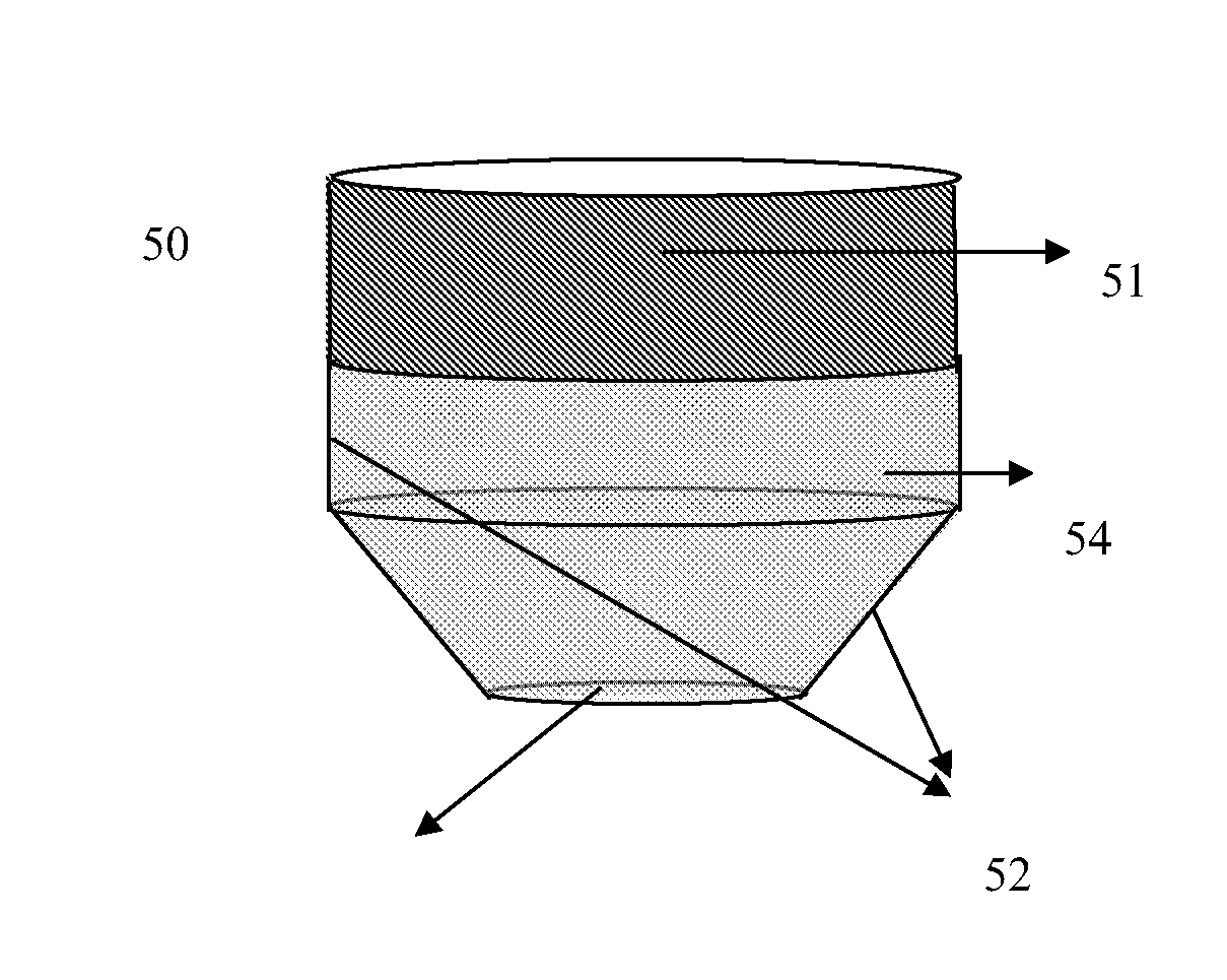
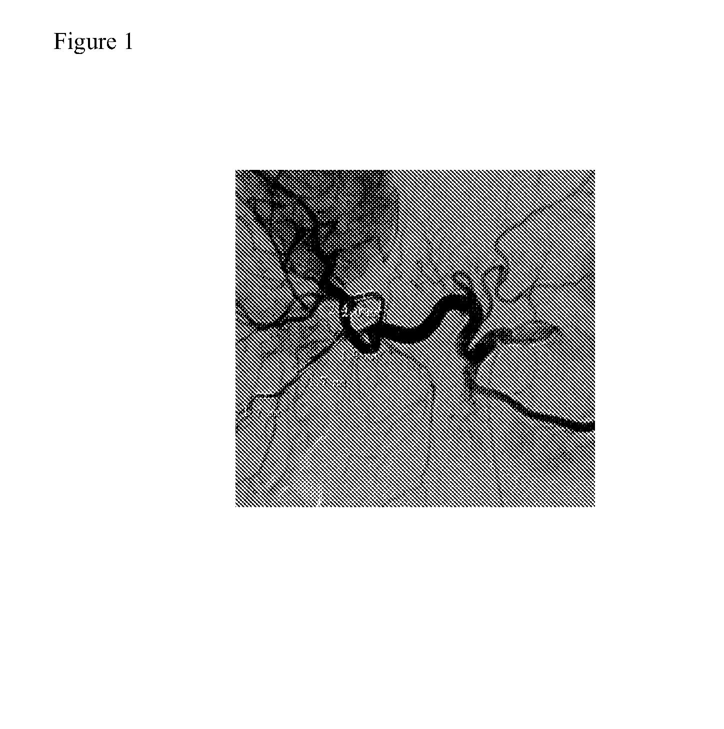
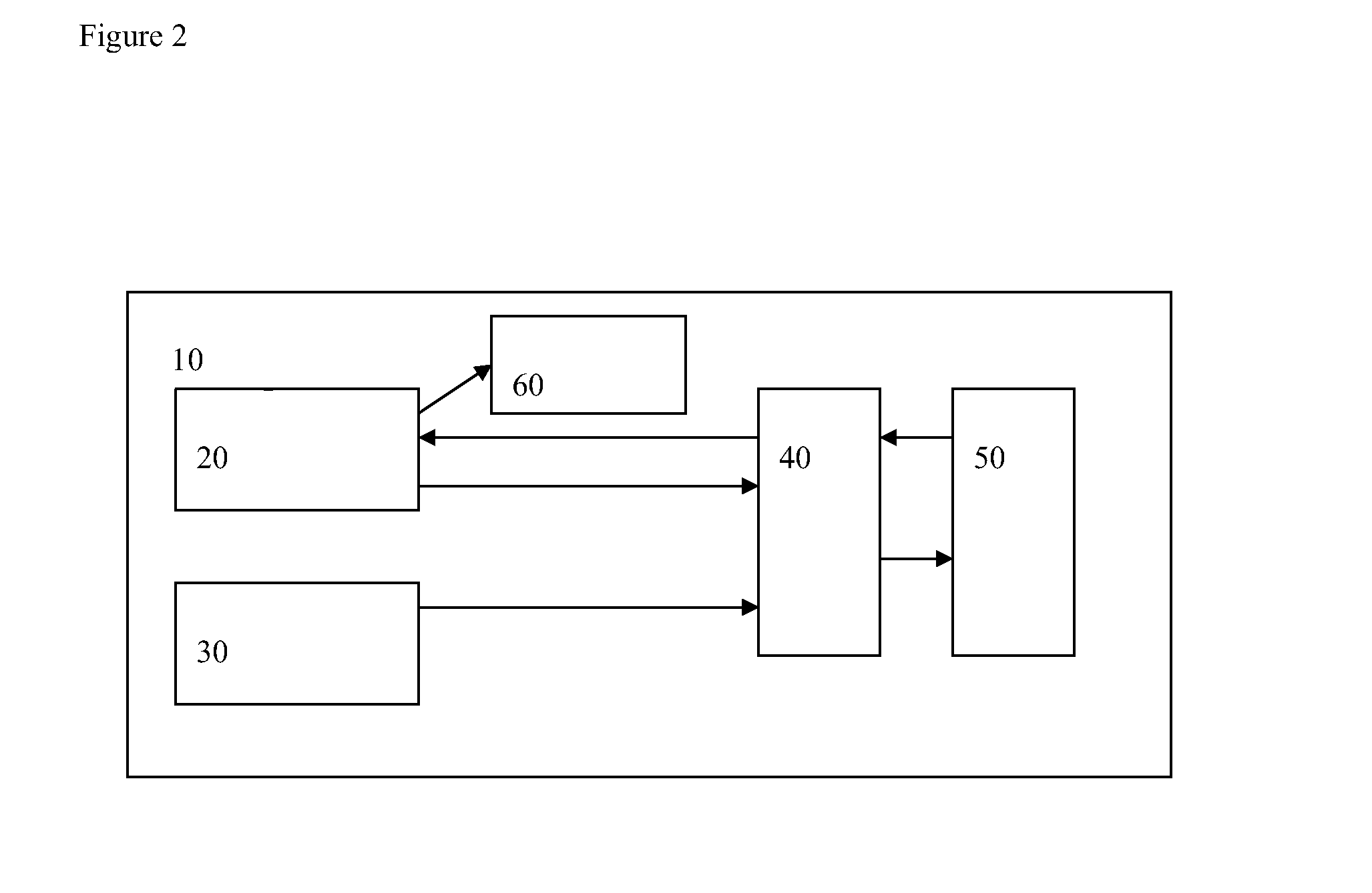
[0027]The key to this device was whether the HIFU therapeutic transducer used for ablation focused ultrasound transducer (51) functioned under mode, and whether it had enough resolving power to resolve the Doppler signal generated in the supply vessels of tumors 1-3 mm in diameter (liver cancer was used as an example here, as in FIG. 1.).[0028]1. The ablation device was assembled as in FIG. 2. The most important device was a diplexer module that could separate the ultrasonic signal scattered from the target, using it as a basis for the calculation of the Doppler signal. The therapeutic processor (20) had a fast A / D function (>50 MHz resolving power) that could calculate the Doppler frequency difference in real time and an audible emitter (60) that emitted sounds of varying loudness and frequencies reflecting the Doppler frequency and magnitude differences. This sound could be used as a feedback for the operator's position and therapeutic efficacy.[0029]2. The plastic device (52) at ...


PUM


Abstract

The present invention relates to a precise blood vessel positioning and high-intensity focused ultrasound ablator by use of one ultrasound transducer.

Description

FIELD OF THE INVENTION[0001]The present invention relates to a system that utilizes one therapeutic ultrasound transducer to be used for both blood vessel positioning diagnosis and high-intensity focused ultrasound (HIFU) ablation therapy.BACKGROUND OF THE INVENTION[0002]According to recent basic and clinical research, HIFU ablation is a highly potent new cancer therapeutic method. Its main advantage is that it is neither invasive nor radioactive, so that it may be repeatedly administered without widespread side effects. However, there are still many problems to be solved before HIFU becoming a mature and widely accepted treatment option. For example, due to the fact that a single HIFU ablation focal spot is only several millimeters in diameter, it takes thousands of focal spots to cover the area of a whole tumor, taking too much time and increasing the risk for patients. Since tumor cells require great amounts of nutrients and oxygen because of their high metabolism and rapid growt...

Claims


Application Information

Patent Timeline
Patent Type & Authority Applications(United States)
IPC IPC(8): A61B8/06A61N7/02
CPCA61B2017/00106A61N7/02A61B2019/5276A61B2017/00128A61B8/4483A61B2090/378
Inventor CHEN, WEN-SHIANGWU, CHIH-CHINGCHEN, CHIUNG-NIENHO, MING-CHIHLEE, PO-HUANG
Owner NAT TAIWAN UNIV
Why Eureka
Try Eureka