
Apparatus and method for characterizing two phase fluid flow

a two-phase fluid and apparatus technology, applied in the field of two-phase fluid flow analysis, can solve the problems of insufficient support for monitoring the fluid flow into and through the injector well for and the inability to recover oil by conventional means, so as to achieve better control and optimization of the injection process.

Inactive Publication Date: 2009-10-29
SCHLUMBERGER TECH CORP
View PDF23 Cites 24 Cited by
  • Summary
  • Abstract
  • Description
  • Claims
  • Application Information

AI Technical Summary

Benefits of technology

[0009]The method and corresponding system of the present invention enable the properties of the two phase fluid flowing into and through the injector well to be monitored for better control and optimization of the injection process.

Problems solved by technology

There are many petroleum bearing formations from which oil cannot be recovered by conventional means because the oil is so viscous that it will not flow from the formation to a conventional oil well.
A large percentage of heavy oil recovery methods use steam injection with different well arrangements, but fail to provide adequate support for monitoring the fluid flow into and through the injector well for control and optimization of the injection process.

Method used


Image

  • Apparatus and method for characterizing two phase fluid flow
  • Apparatus and method for characterizing two phase fluid flow
  • Apparatus and method for characterizing two phase fluid flow

Examples


Embodiment Construction

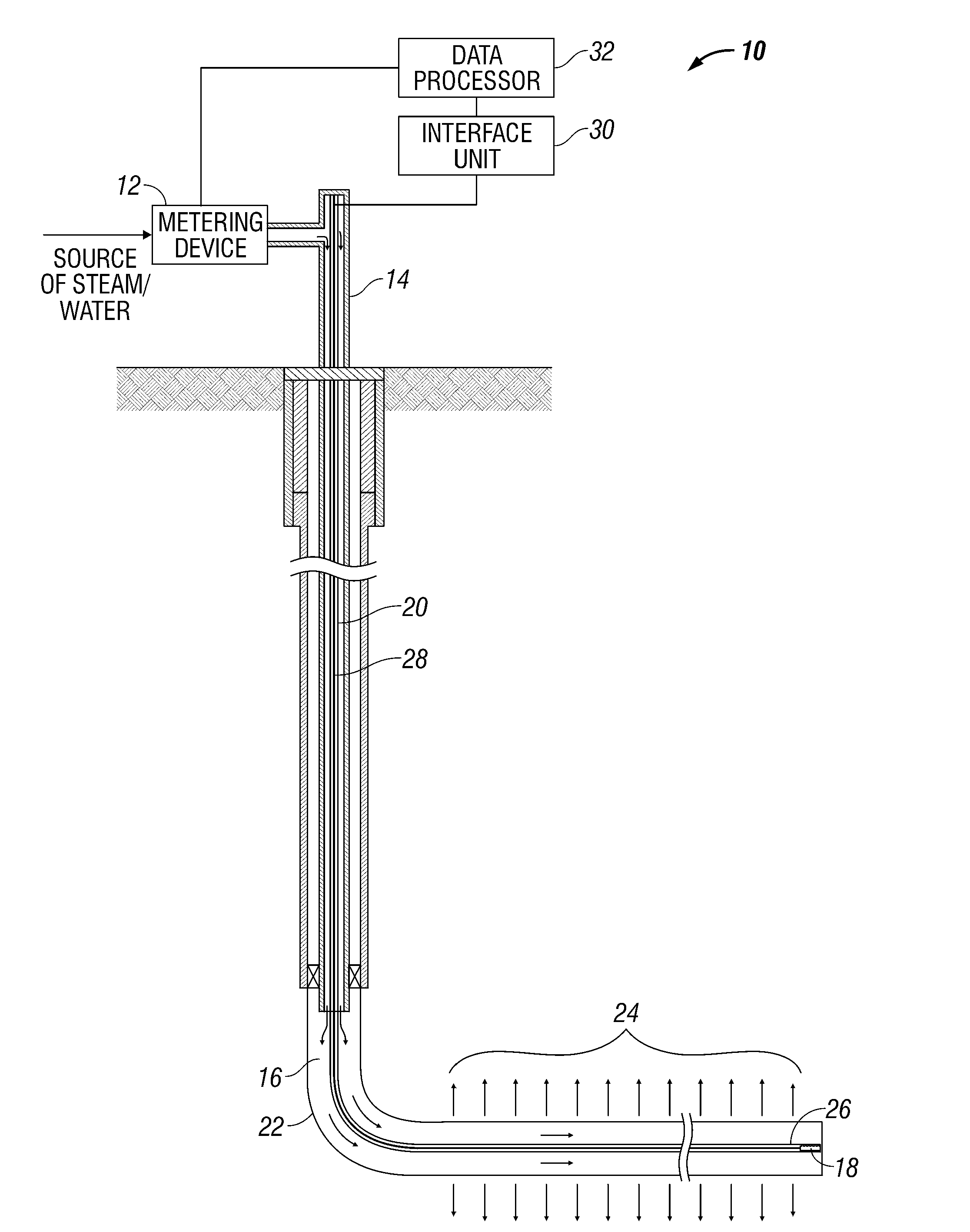
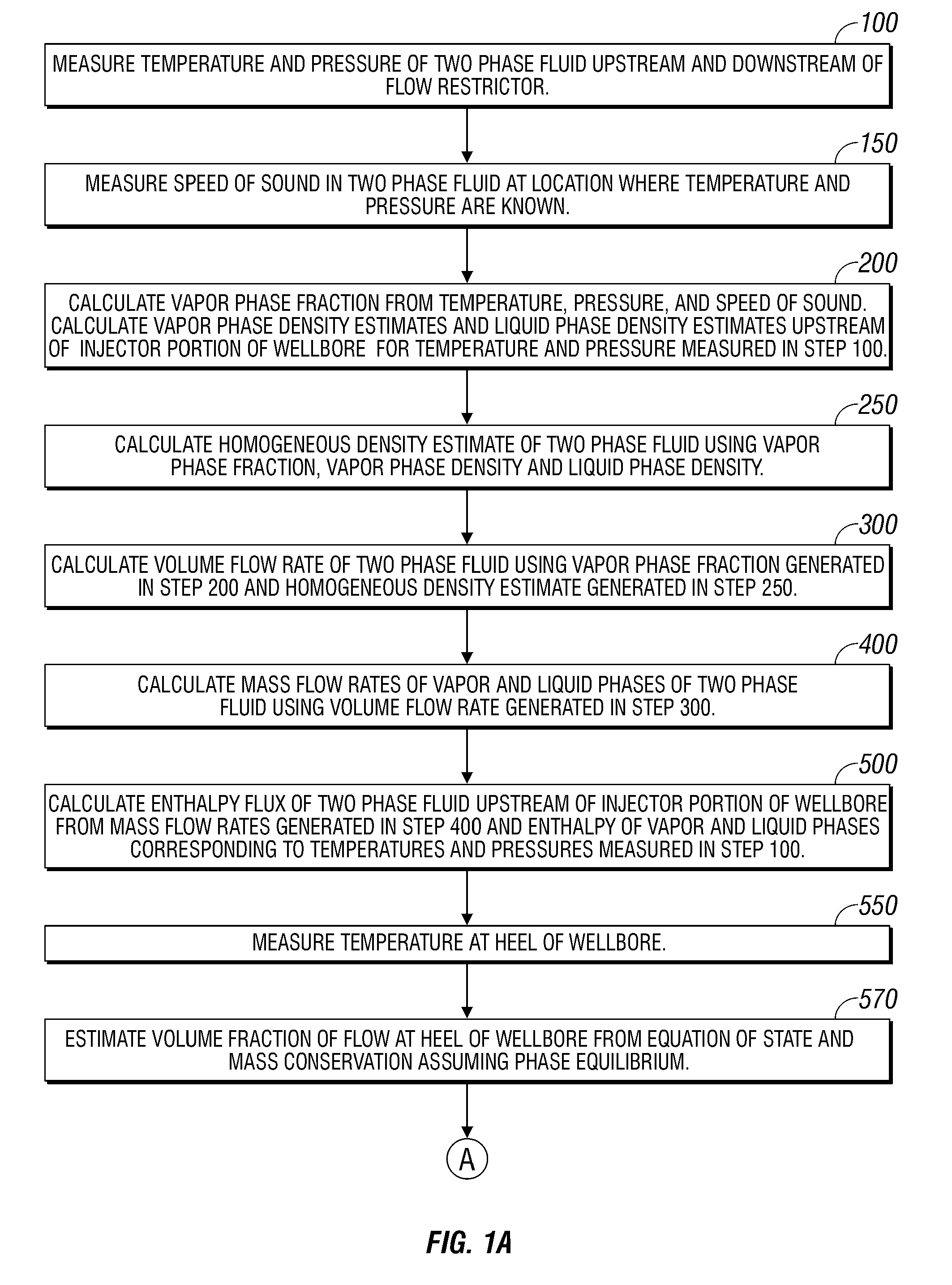
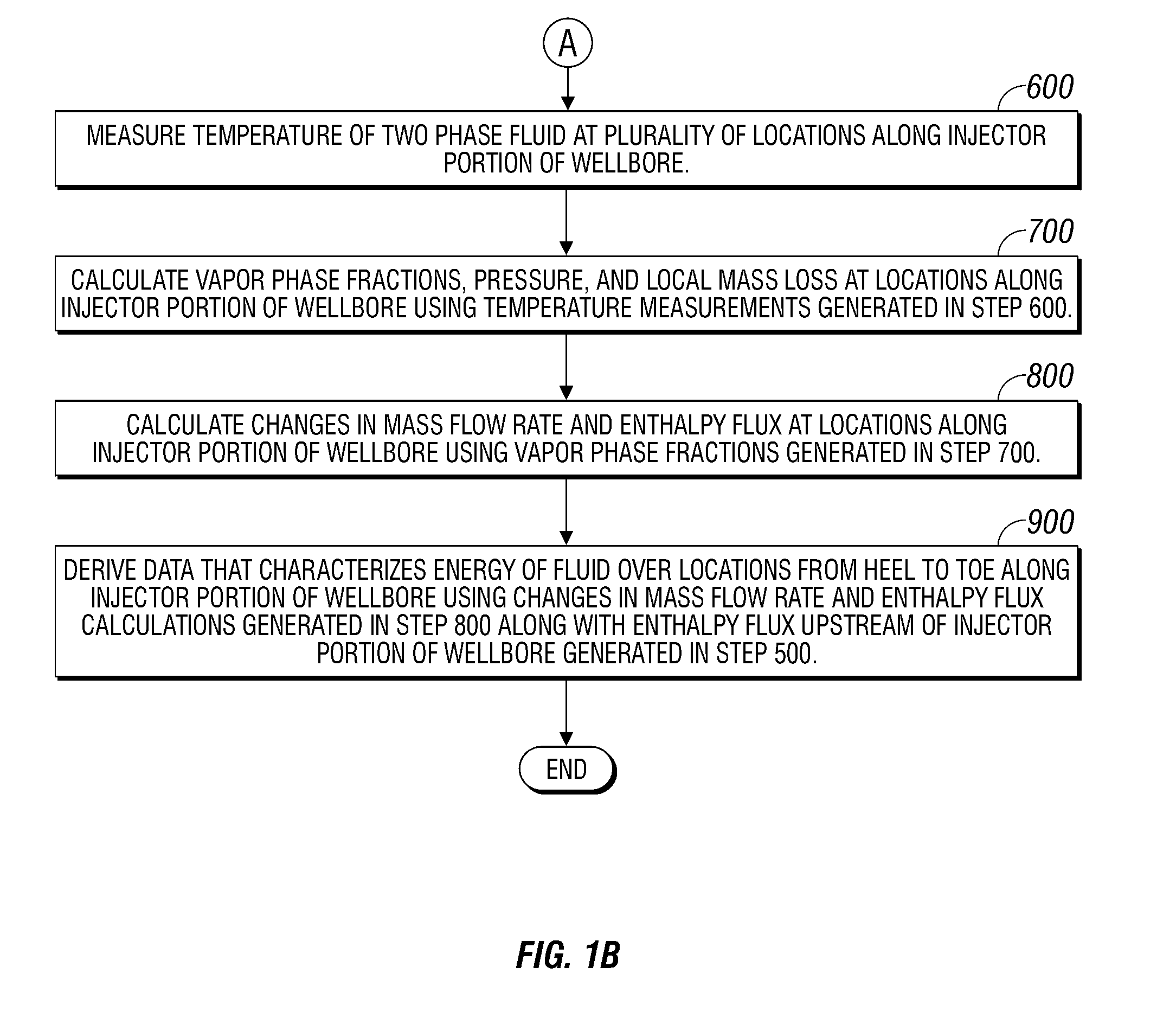
[0018]Turning to FIGS. 1A and 1B there is shown a method for determining a number of fluid properties of a two phase fluid (e.g., steam and water) flowing upstream of an injector portion of a wellbore (FIG. 3) as well as a number of fluid properties of the two phase fluid along the injector portion of the wellbore.

[0019]The enthalpy (heat content) of the two phase fluid upstream of the injector portion the wellbore is given by the following equation:

ht=myhv(T,P)+mlhl(T,P)   (1)

[0020]where mv is the mass of the vapor phase of the two phase fluid.[0021]hv(T,P) is the enthalpy of the vapor phase of the two phase fluid at temperature T and pressure P.[0022]ml is the mass of the liquid phase of the two phase fluid, and[0023]hl(T,P) is the enthalpy of the liquid phase of the two phase fluid at temperature T and pressure P.

It is assumed that the vapor and liquid phases of the two phase fluid are in equilibrium along the wellbore, and thus that that their respective enthalpy values vary as ...


PUM


Abstract

An apparatus (and corresponding method) for characterizing the fluid properties of a two phase fluid includes a restriction element (e.g., orifice plate or nozzle) along the flow path of the two phase fluid. At least one temperature sensor measures temperature of the two phase fluid flowing through the restriction element. A pressure sensor measures the pressure downstream of the restriction element. Time-of-flight measurements of pulses passing through the two phase fluid are made. The speed of sound within the two phase fluid is calculated from the time-of-flight measurements. At least one fluid property (e.g., a vapor phase fraction) of the two phase fluid is calculated from the measured pressure, the measured temperature, and the calculated speed of sound.

Description

CROSS-REFERENCE TO RELATED APPLICATION[0001]This application is related to application Ser. No. ______, filed Apr. 25. 2008, entitled “Method, Apparatus and System for Characterizing Two Phase Fluid Flow in an Injection Well”.BACKGROUND OF THE INVENTION[0002]1. Field of the Invention[0003]This invention relates broadly to the analysis of two phase fluid flow.[0004]2. Description of Related Art[0005]There are many petroleum bearing formations from which oil cannot be recovered by conventional means because the oil is so viscous that it will not flow from the formation to a conventional oil well. Examples of such formations are the bitumen deposits in Canada and the United States and the heavy oil deposits in Canada, the United States, and Venezuela. In these deposits, the oil is so viscous under the temperatures and pressures prevailing within the formations that it flows very slowly (or not at all) in response to the force of gravity. Heavy oil is an asphaltic, dense (low API gravit...

Claims


Application Information

Patent Timeline
Patent Type & Authority Applications(United States)
IPC IPC(8): G01F1/74
CPCE21B43/24E21B47/06E21B47/10G01N25/60G01F1/50G01F1/74G01F1/88G01F1/42
Inventor MONMONT, FRANCK BRUNO JEANOHMER, HERVEODDIE, GARY MARTINPEATS, ALLAN
Owner SCHLUMBERGER TECH CORP
Learn More