
Stratified Charge Gasoline Direct Injection Systems Using Exhaust Gas Recirculation

a gasoline direct injection and gas recirculation technology, applied in brake systems, process and machine control, instruments, etc., can solve the problems of engine instability, gdi systems running at lean conditions may require relatively expensive after treatment systems, and may fail to achieve various emissions standards. achieve the effect of improving the knock-tolerance of the engine and reducing emissions

Active Publication Date: 2009-10-29
SOUTHWEST RES INST
View PDF34 Cites 16 Cited by
  • Summary
  • Abstract
  • Description
  • Claims
  • Application Information

AI Technical Summary

Benefits of technology

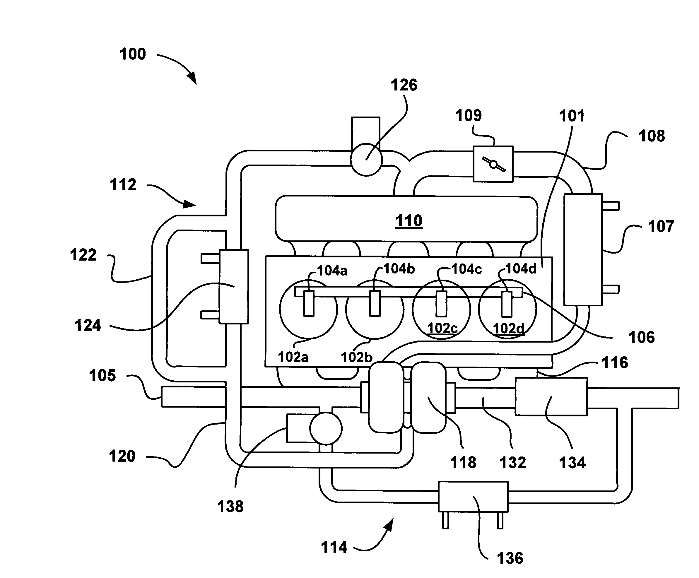
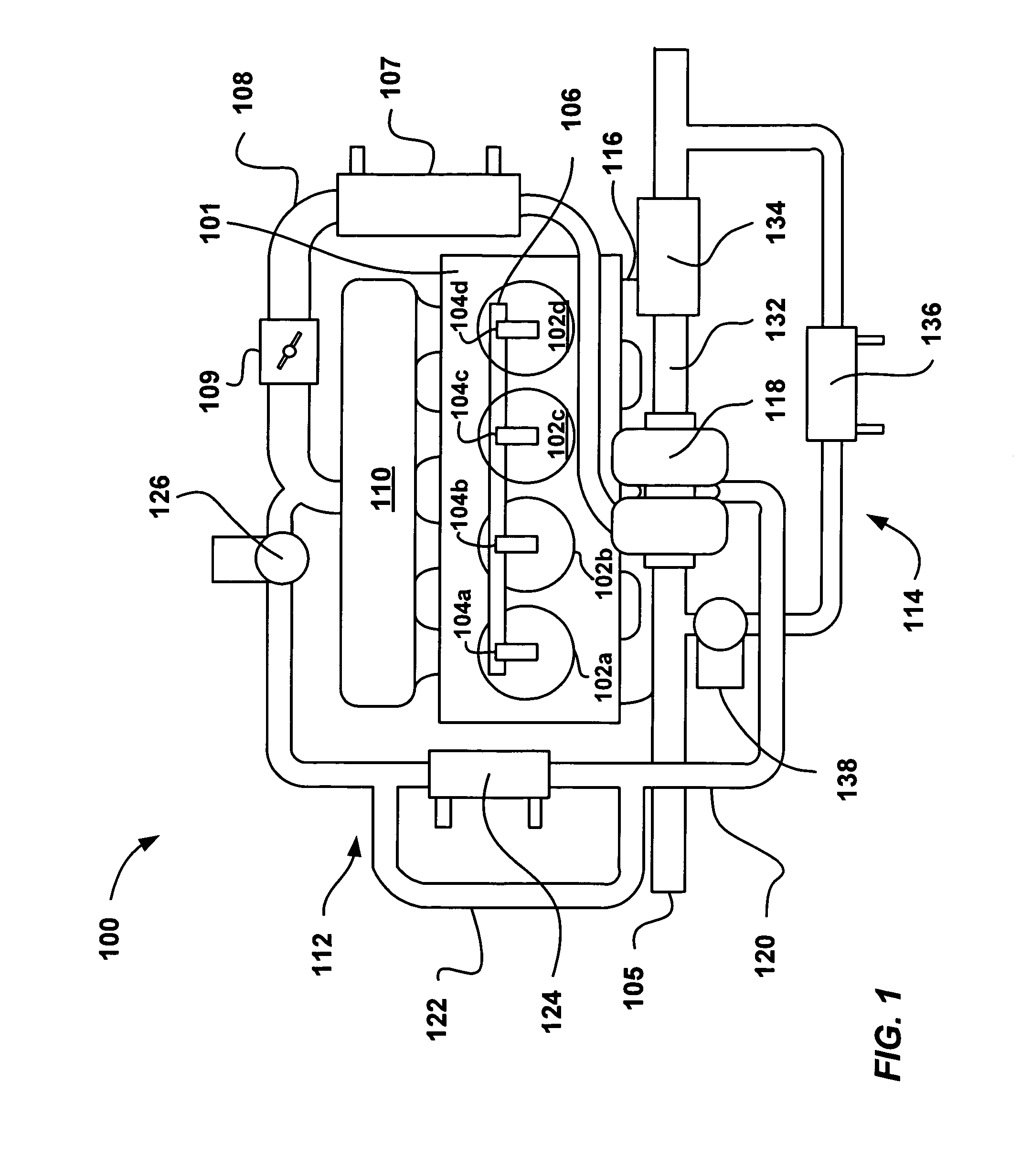
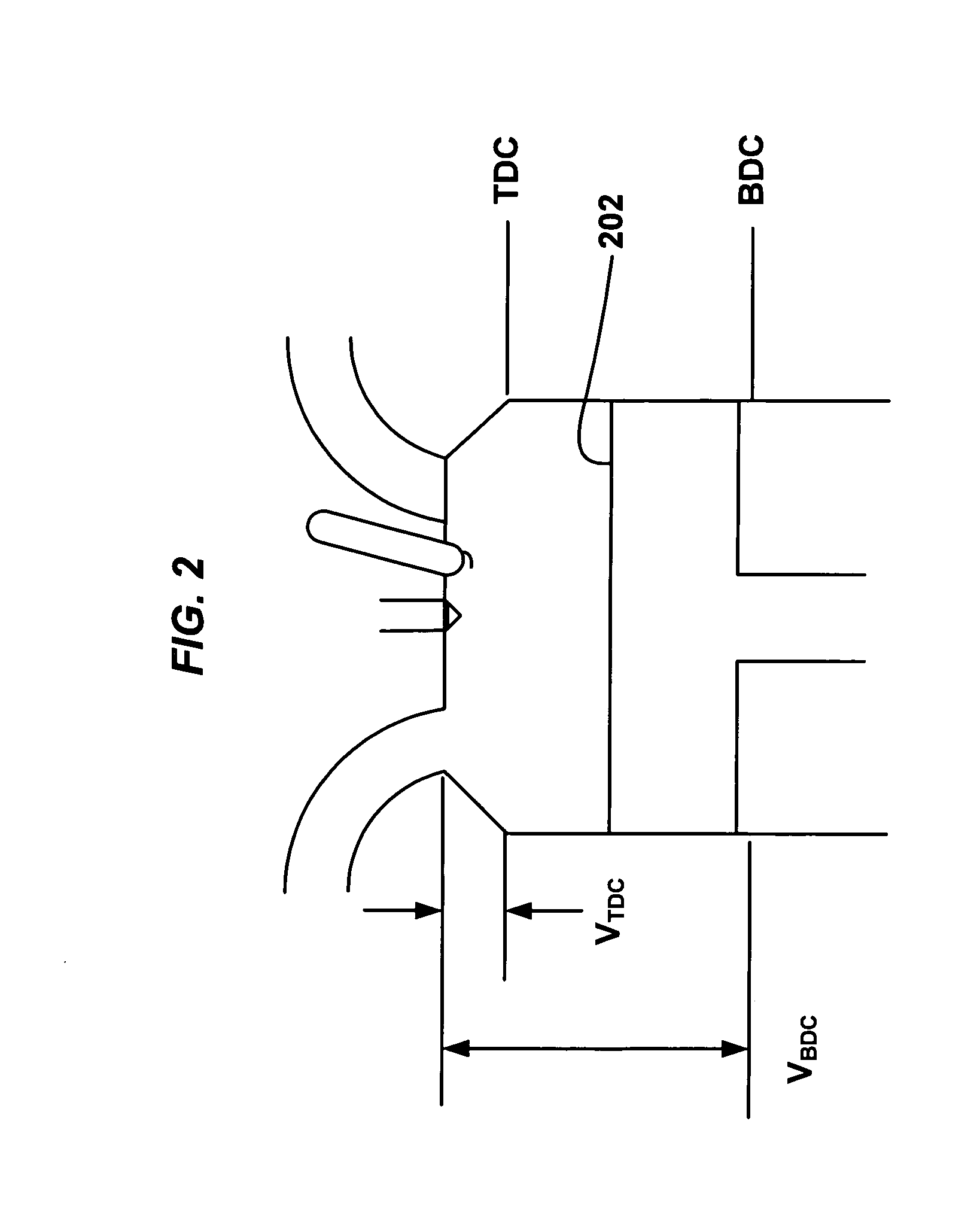
[0008]An aspect of the present disclosure relates to a method of reducing emissions and improving knock-tolerance in an engine. The method may include providing air, including exhaust gas present at levels greater than 20% by total air mass, and introducing the air, including the exhaust gas, into a combustion chamber having a volume including a piston and a cylinder head. A first amount of fuel may be directly injected into the combustion chamber, when the piston is moving away from the cylinder head, and a second amount of fuel may be directly injected into the combustion chamber, when the piston is moving towards the cylinder head. The first and second amounts of fuel may then be ignited wherein the ratio of the air to the first and second amounts of fuel is 14.0:1 to 15.0:1.

Problems solved by technology

However, running GDI systems at lean conditions may require relatively costly after treatment systems or may fail in attaining various emissions standards.
However, this may not be true across all engine speeds and loads, such as low loads of 5 bar and less, as increased EGR amounts may lead to engine instability as reflected by an increase in cov imep.

Method used


Image

  • Stratified Charge Gasoline Direct Injection Systems Using Exhaust Gas Recirculation
  • Stratified Charge Gasoline Direct Injection Systems Using Exhaust Gas Recirculation
  • Stratified Charge Gasoline Direct Injection Systems Using Exhaust Gas Recirculation

Examples


Embodiment Construction

[0016]It is to be understood that this disclosure is not limited in its application to the details of construction and the arrangement of components set forth in the following description or illustrated in the drawings. The embodiments herein are capable of other embodiments and of being practiced or of being carried out in various ways. Also, it is to be understood that the phraseology and terminology used herein is for the purpose of description and should not be regarded as limiting. The use of “including,”“comprising,” or “having” and variations thereof herein is meant to encompass the items listed thereafter and equivalents thereof as well as additional items. Unless limited otherwise, the terms “connected,”“coupled,” and “mounted,” and variations thereof herein are used broadly and encompass direct and indirect connections, couplings, and mountings. In addition, the terms “connected” and “coupled” and variations thereof are not restricted to physical or mechanical connections ...


PUM


Abstract

An aspect of the present disclosure relates to a method and system for reducing emissions and improving knock-tolerance in an engine. Air, including exhaust gas present at levels greater than 20% by total air mass, may be introduced into a combustion chamber having a volume including a piston and a cylinder head. A first amount of fuel and a second amount of fuel may be directly injected into the combustion chamber at various points during the cycle, wherein the ratio of the air, including the exhaust gas, to the first and second amounts of fuel is 14.0:1 to 15.0:1. The first and second amounts of fuel may then be ignited. An electronic control unit may be utilized to time the injections and control the introduction of exhaust gas.

Description

CROSS REFERENCES TO RELATED APPLICATIONS[0001]None.STATEMENT REGARDING FEDERALLY SPONSORED RESEARCH OR DEVELOPMENT[0002]None.REFERENCE TO SEQUENTIAL LISTING, ETC.[0003]None.FIELD OF THE INVENTION[0004]The present disclosure relates generally to the use of gasoline direct injection systems and, in particular, the use of a stratified charge to improve stability at relatively high exhaust gas recirculation levels.BACKGROUND[0005]In gasoline direct injection (GDI) systems fuel may be injected at relatively higher pressures over a common rail system directly into the combustion chamber of an engine. Gasoline direct injection allows for stratified charge, wherein the air / fuel mixture may be layered. A rich portion of the air to fuel mixture may be directed around the spark plug and fresh air or a mix having a relatively lower air to fuel ratio may be present around the richer portion. In addition, GDI systems may be run at relatively lean conditions, where air to fuel ratios may be 50:1 o...

Claims


Application Information

Patent Timeline
Patent Type & Authority Applications(United States)
IPC IPC(8): F02M25/07
CPCF02B29/0437F02M25/0707F02M25/0709Y02T10/146F02M25/0732Y02T10/121F02M25/0728F02M26/05F02M26/06F02M26/24F02M26/25Y02T10/12
Inventor ALGER, II, TERRENCE FRANCISROBERTS, JR., CHARLES EDWARDMEHTA, DARIUS
Owner SOUTHWEST RES INST
Learn More