Organic light emitting apparatus and method of producing the same

a light-emitting apparatus and organic technology, applied in the direction of discharge tube luminescnet screens, discharge tube/lamp details, electric discharge lamps, etc., can solve the problems of deterioration of display, peeling or cracking of sealing layer, and deterioration of properties, so as to suppress the deterioration of light-emitting

Active Publication Date: 2009-10-29
CANON KK
View PDF9 Cites 4 Cited by
  • Summary
  • Abstract
  • Description
  • Claims
  • Application Information

AI Technical Summary

Benefits of technology

[0017]According to the present invention, individual organic light emitting apparatuses can be divided without causing damage to a sealing layer such as peeling or cracking in a step of dividing individual organic light emitting apparatuses from a substrate on which plural organic light emitting apparatuses are formed. As a result, it can prevent moisture or a gas component from infiltrating into a stack layer completely, whereby an organic light emitting apparatus having a long lifetime in which the deterioration of light emission is suppressed can be obtained.

Problems solved by technology

The organic EL device is liable to cause the deterioration of its properties owing to moisture or oxygen; a trace amount of moisture peels the stack layer off of an electrode layer, and the peeling is responsible for the occurrence of a dark spot.
However, when individual organic light emitting apparatuses are divided by employing a general scribing approach from a substrate on which plural organic light emitting apparatuses are formed, the peeling or cracking of a sealing layer occurs at a position where the apparatus is to be divided.
As a result, moisture or a gas component infiltrates into a stack layer, thereby leading to the deterioration of display.

Method used


Image

  • Organic light emitting apparatus and method of producing the same
  • Organic light emitting apparatus and method of producing the same
  • Organic light emitting apparatus and method of producing the same

Examples


example 1

[0060]This example will be described with reference to FIGS. 9A and 9B. FIG. 9A is a sectional view schematically illustrating a part taken out of an evaluation sample, and FIG. 9B is a top view schematically illustrating the part.

[0061]In this example, the evaluation sample was produced as illustrated in each of FIGS. 9A and 9B, and was evaluated for the presence or absence of the infiltration of moisture from a division position on the basis of a change in transmittance due to Ca corrosion. The transmittance of a Ca film changes as a result of a reaction between the Ca film and water or oxygen.

[0062]A three-dimensional portion A having a height of 0.5 μm, a width of 1 μm, and a taper angle of 55° was formed in a line shape on a substrate obtained by forming an insulating layer on a glass base material. Next, a Ca film 13 having a thickness of 1,000 Å was formed by vapor deposition partially at the central portion of the substrate at the position distant from the three-dimensional ...

example 2

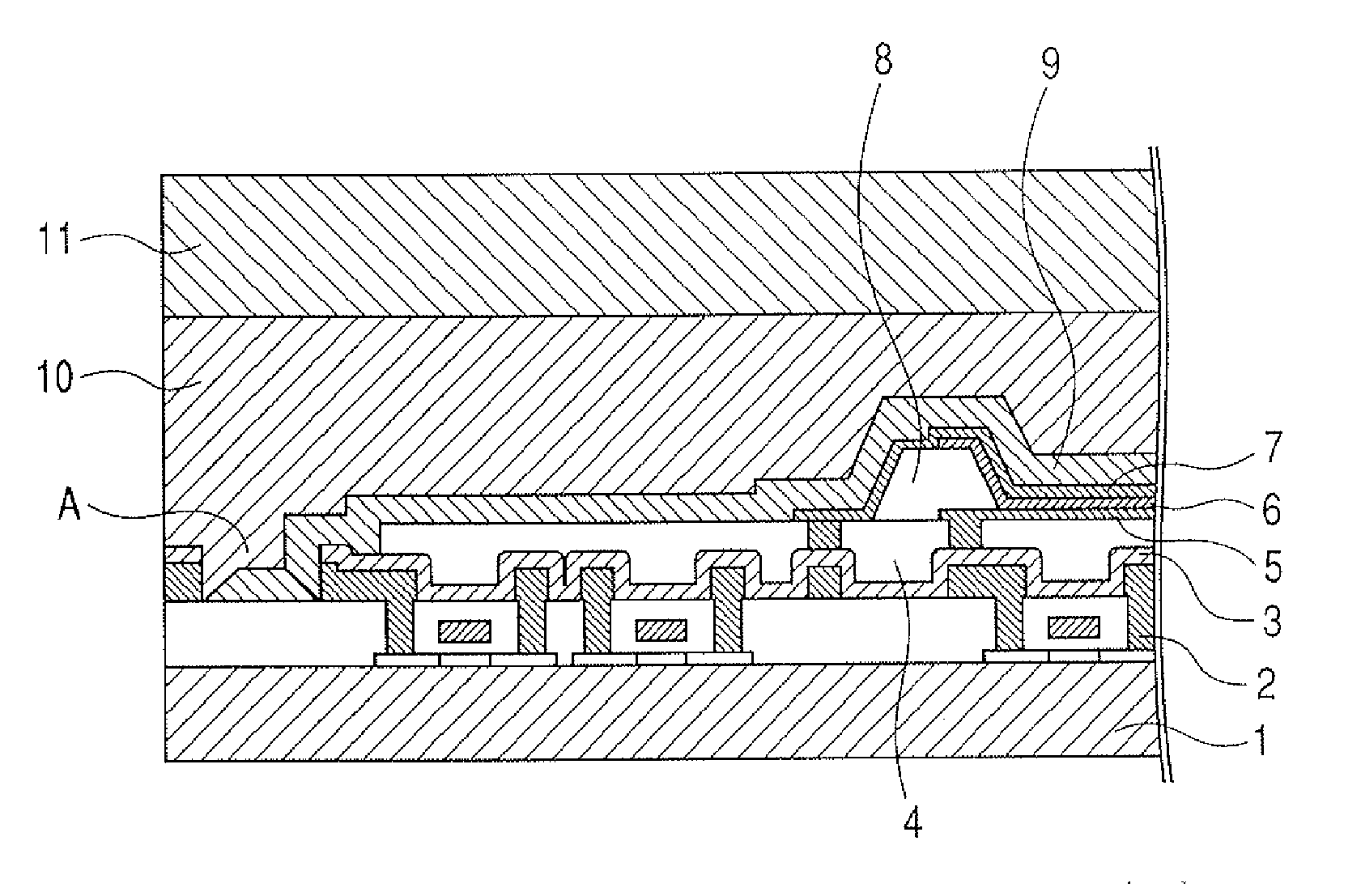
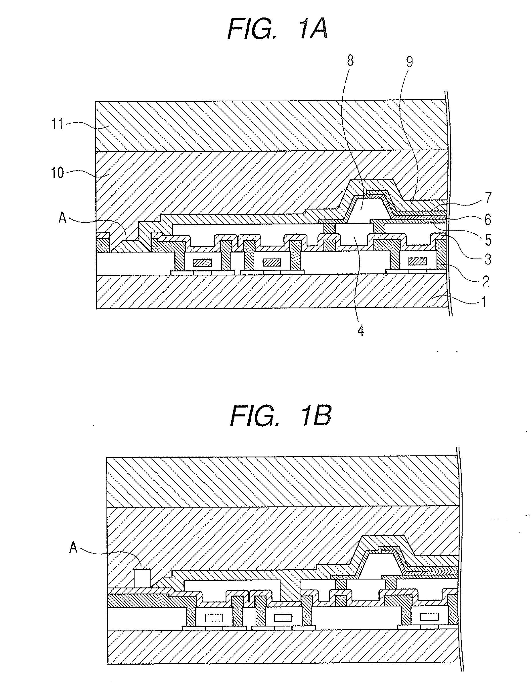
[0075]This example will be described with reference to FIGS. 1A, 2 and 8A.

[0076]In this example, an organic light emitting apparatus illustrated in FIG. 1A was produced, and was evaluated for light emitting property.

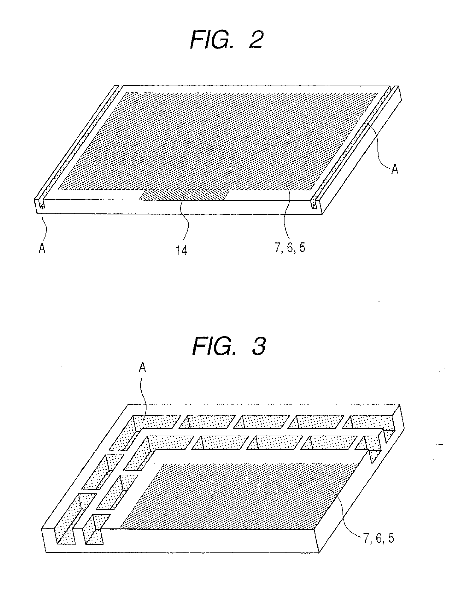
[0077]In this example, organic light emitting apparatuses each having the constitution illustrated in FIG. 1A were formed on a large substrate so as to be adjacent to each other. Each organic light emitting apparatus was divided after the formation of the sealing layer 9. As illustrated in FIG. 2, the three-dimensional portions A were formed between adjacent organic light emitting apparatuses on two sides except the side on which a power source and the signal supply pad 14 were formed and a side opposed to the side.

[0078]As illustrated in FIG. 8A, three three-dimensional portions A each having a concave structure with a depth of 0.5 μm, a width of 5 μm, and a taper angle of 60° were formed from a position distant from the division position B by 0.1 mm toward a display re...

example 3

[0083]This example will be described with reference to FIGS. 1A, 2 and 8B.

[0084]In this example, an organic light emitting apparatus similar to that of Example 2 was produced, and was evaluated for light emitting property; provided that, in this example, as illustrated in FIG. 8B, a concave structure having a depth of 0.5 μm, a width of 100 μm, and a taper angle of 60° was formed as a three-dimensional portion A so as to straddle the division position B, and, furthermore, three three-dimensional portions A each having a depth of 0.5 μm, a width of 5 μm, and a taper angle of 60° were formed from an end of the concave structure toward a display region side at a variable pitch of 30 μm, 20 μm, and 10 μm.

[0085]The division position of the organic light emitting apparatus of this example was observed with an optical microscope and an SEM. As a result, a crack and peeling were observed in the sealing layer 9. However, none of a crack and peeling was observed in the sealing layer 9 on the ...


PUM


Abstract

Provided are an organic light emitting apparatus for use in, for example, a flat device display, and a method of producing the apparatus. The organic light emitting apparatus has sides formed by division at ends of its substrate. Three-dimensional portions are formed on the surface of the substrate along the sides. An inorganic sealing layer is formed to extend toward the three-dimensional portions.

Description

BACKGROUND OF THE INVENTION[0001]1. Field of the Invention[0002]The present invention relates to an organic light emitting apparatus for use in, for example, a flat device display, and a method of producing the apparatus.[0003]2. Description of the Related Art[0004]An organic light emitting apparatus having an organic electroluminescence (EL) device as a self light emitting device has been recently attracting attention because of its potential to serve as a flat device display. The organic EL device is obtained by laminating at least a first electrode, a stack layer including an organic light emitting layer, and a second electrode in the stated order on a substrate. The organic EL device is liable to cause the deterioration of its properties owing to moisture or oxygen; a trace amount of moisture peels the stack layer off of an electrode layer, and the peeling is responsible for the occurrence of a dark spot. In view of the foregoing, the organic EL device is covered with an etching...

Claims


Application Information

Patent Timeline
Patent Type & Authority Applications(United States)
IPC IPC(8): H01L51/54H01L21/56H01L21/78
CPCH01L51/56H01L51/5237H10K50/844H10K71/00H05B33/04
Inventor YAMAZAKI, TAKURONAGAYAMA, KOHEI
Owner CANON KK
Why Eureka
Try Eureka