Method and device for rapid non-destructive quality control of powdered materials

a non-destructive and powdered technology, applied in the direction of resistance/reactance/impedence, instruments, material analysis, etc., can solve the problems of not being able to achieve rapid quality control of powdered materials, and consuming a great deal of tim

Inactive Publication Date: 2009-10-29
ENERIZE CORP
View PDF1 Cites 8 Cited by
  • Summary
  • Abstract
  • Description
  • Claims
  • Application Information

AI Technical Summary

Benefits of technology

[0019]The electromagnetic capacitance method of powder quality control involves placing the powder within the electric field of a capacitor and the determination of its properties based on the corresponding response of the electric field source. Powdered materials such as dry cements...

Problems solved by technology

General chemical analysis, if conducted for testing purposes, can consume a great ...

Method used


Image

  • Method and device for rapid non-destructive quality control of powdered materials
  • Method and device for rapid non-destructive quality control of powdered materials
  • Method and device for rapid non-destructive quality control of powdered materials

Examples


example 1

[0094]The cylindrical capacitive transducer has copper electrodes that are 70 mm×30 mm with a thickness of 10-20 μm. The electrodes are made as half-cylinders and mounted inside the lower part of the trasducer case made of dielectric in a cylinder-like form. The diameter of the dielectric is 60 mm and the height is 70 mm. The thickness of the wall in the areas of electrodes is 1.00 mm. As an auxiliary induction for the circuit, a coil with a diameter of 18 mm, together with two wire coils with an outside diameter of 0.84 mm was connected to it is used.

[0095]Since the height of the entire cylindrical part of the capacitive transducer is commensurable with the entire height of the transducer L1 and compatible with the height of the copper electrode L2 the capacitance is described by the expression (16):

C=ɛ0ɛrL2πlnsin(φ3-φ02)sin(φ2-φ12)sin(φ2-φ02)sin(φ3-φ12),(16)

where:[0096]∈0=8.854×10⁻¹²,[0097]∈r=∈′=1,[0098]Φ—are the values of angles of electrode segment in a cylindrical co-ordinate s...

example 2

[0113]A capacitive transducer is made of two parallel electrodes of copper foil of size 120 mm×30 mm with a thickness of 20 microns. Electrodes are placed inside the lower part of dielectric transducer case. The distance between the electrodes is 4 mm. The thickness of dielectric wall in the area of electrodes is 1 mm. In the case when the total area of condenser parallel plates is large, such that the electric field distorting effect can be ignored on the plate edges, Gauss's law was applied:

C=∈0∈′S / d=8.854×10⁻¹²×∈′S / d=7.969 pF,  (19)

[0114]In this case, transducer capacitance is higher as compared with the cylindrical transducers in Example 1. The increased capacitance as compared with Example 1 allows increased sensitivity. Measurements were made by the instrument described in Example 1. The same samples of cement-based compositions were used.

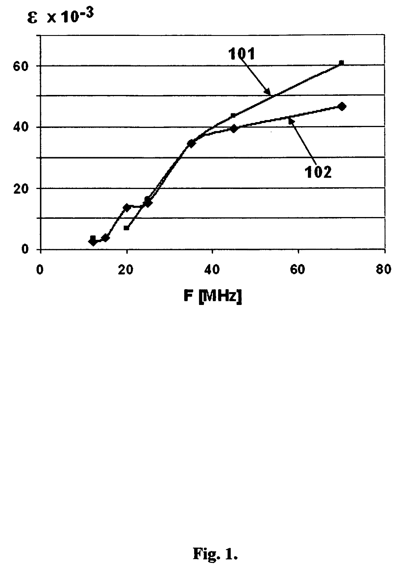
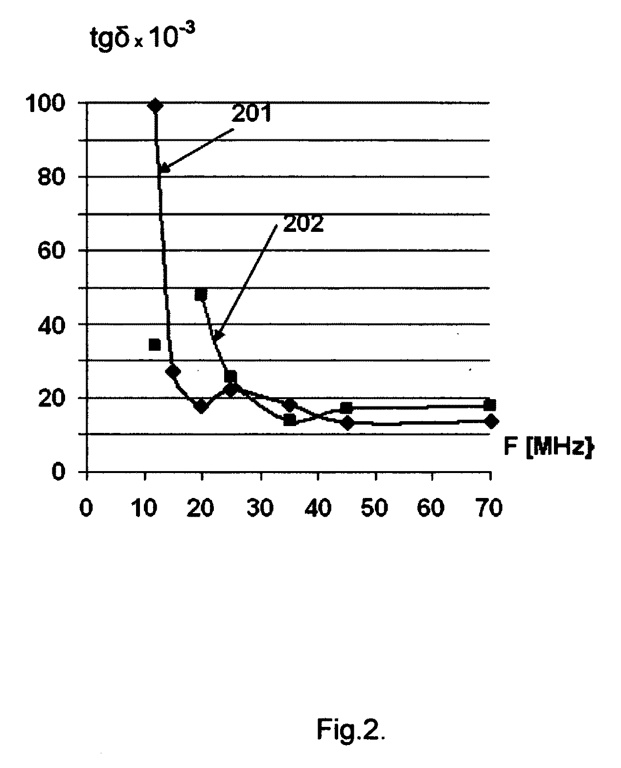
[0115]The results of measurements are presented in Table 2. On the basis of these data diagrams were drawn (FIG. 3-6), which illustrates the...

example 3

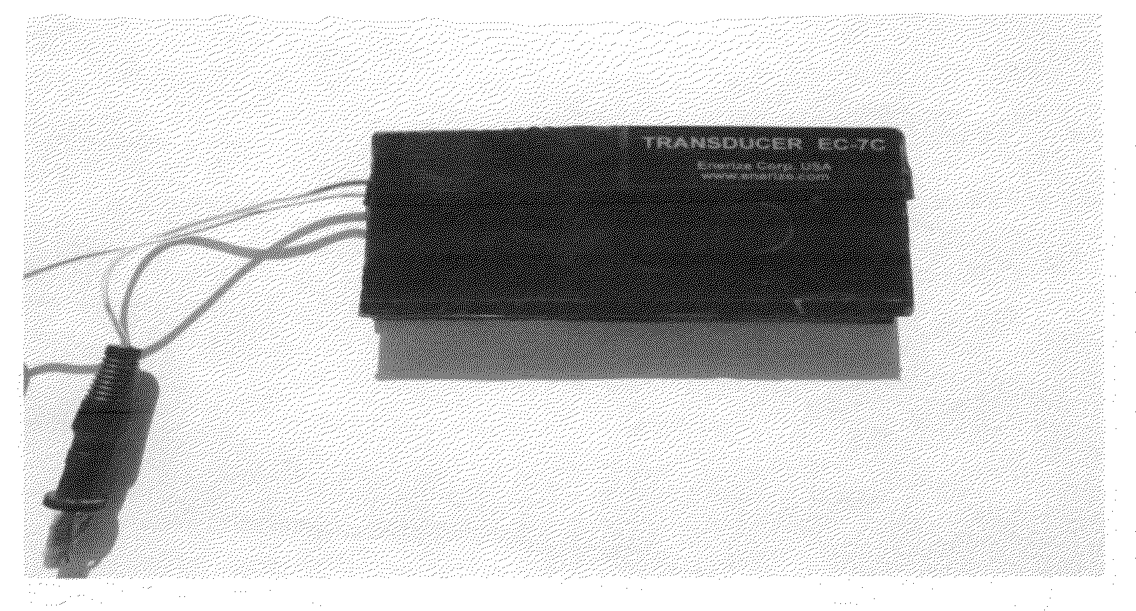
[0120]In this example, results of powder testing using transducer EC-5C are shown (FIG. 7). The transducer has parallel flat electrodes of copper foil. Electrodes sizes are: a=100 mm, b=12.5 mm and thickness=15 microns. Electrodes are mounted inside the lower part of a transducer case. The case is made of dielectric. The thickness of the wall in the area of the electrodes is 1 mm. The distance between electrodes L is 7 mm. The increased distance between electrodes is needed to ensure even filling of the space between electrodes when a transducer is inserted into the powder being tested.

[0121]To compute capacitance of a capacitor with increased space between electrodes equations (6 and 7) were applied. The equation takes into account the distortion of the field at the capacitor edges caused by the electrodes plates.

C=4ɛabl+0.5C0,(21)

where;

C0≅16ɛaabarcshba+arcshab.(22)

[0122]The resulting capacitance value is C=2.45 pF.

[0123]An experimental measurement of the transducer capacitance ove...


PUM


Abstract

Method and related device intended for rapid non-destructive testing of powdered materials with low electric conductivity such as cement and cement-based compositions through determination of their electrical properties. The invention involves an electromagnetic method, including an electronic circuit for generating an electric field in a capacitance probe that is inserted into the powder to be tested. Electrical properties of powdered materials are determined on the basis of a set of the values for a set of parameters including quality factor (Q-factor), capacitance, dissipation factor, and dielectric permeability of the material. These parameter values can be related to such characteristics as moisture content, particle size, and material composition. The method and device can indicate the differences between the samples with various quantities of unwanted components or reaction products, and the extent of sample ageing.

Description

CROSS-REFERENCE TO RELATED APPLICATIONS[0001]Claims priority of Provisional Patent Application No. 61 / 124,984, Filed Apr. 21, 2008FEDERALLY SPONSORED RESEARCH[0002]NoneSEQUENCE LISTING[0003]NoneFIELD OF THE INVENTION[0004]The present invention relates to non-destructive testing for determination of electrical and associated properties such as composition, moisture content, and particle size, of bulk materials, and especially as related to the quality control of powdered materials such as cement.BACKGROUND OF THE INVENTION[0005]Physical and chemical properties of powdered materials may be critical parameters in a variety of industrial applications. Among many examples are the construction industry, wherein properties of cement have to be controlled, or the manufacture of lithium-based batteries where properties of the initial powdered electrode active materials must be tested, or in case of super capacitors and in other areas. General chemical analysis, if conducted for testing purpo...

Claims


Application Information

Patent Timeline
IPC IPC(8): G01N27/22G01R27/26
CPCG01N27/221
Inventor REDKO, VOLODYMYR I.SHEMBEL, ELENA M.KHANDETSKYY, VOLODYMYR S.SIVTSOV, DMYTROPASTUSHKIN, TYMOFIYRED'KO, OXANAWILSON, BARY WALLACE
Owner ENERIZE CORP
Why Eureka
Try Eureka