Optical absorption gas analyser

a gas analyser and optical absorption technology, applied in the field of optical absorption gas analysers, can solve the problems of low cost design, inability to provide any kind of compensation for instrument drift, and inability to provide a separate, sealed gas reference cell containing inert gas, etc., and achieve the effect of economising battery power and high efficiency

Active Publication Date: 2009-10-29
BAH HLDG
View PDF7 Cites 35 Cited by
  • Summary
  • Abstract
  • Description
  • Claims
  • Application Information

AI Technical Summary

Benefits of technology

[0041]The analyser could be connected to an external power source in order to supply power to the radiation source and processing components. However, it is preferred that that the analyser further comprises a power source so that the device is fully portable. Preferably the power source comprises a battery, solar cell or solar-powered battery. In particularly preferred embodiments, a highly efficient solar battery (up to 28% efficient) is provided, which can deliver several milliwatts of energy even in lo

Problems solved by technology

This type of instrument is relatively inexpensive, but does not provide any kind of compensation for instrument drift over time which may occur due to the radiation source and/or the photodetector ageing, or accumulation of dirt and dust in the optical path, for example.
Such sensors can work with good stability with the two channels working on the same wavelength (corresponding to an absorption line of the target gas), but the requirement for a separate, sealed gas reference cell containing an inert gas is a serious limitation in a portable, low cost design.
However, such radiation sources are slow (typically, the response time is more than 100 milliseconds) and has significant power consumption (200 milliwatts or more).
As such, these components are not suitable for portable, low power sensors which can typically support a power consumption of no more than 1-2 milliwatts.
However, LEDs suffer from the problem that their output power and emitted radiation wavelength depend significantly on temperature

Method used


Image

  • Optical absorption gas analyser
  • Optical absorption gas analyser
  • Optical absorption gas analyser

Examples


first embodiment

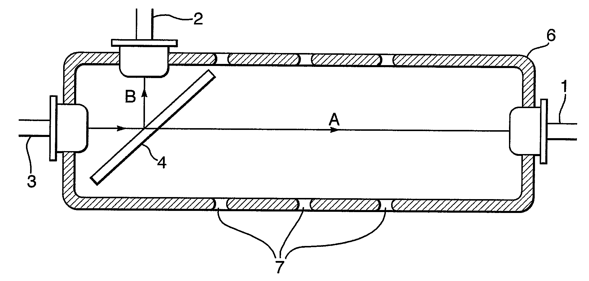
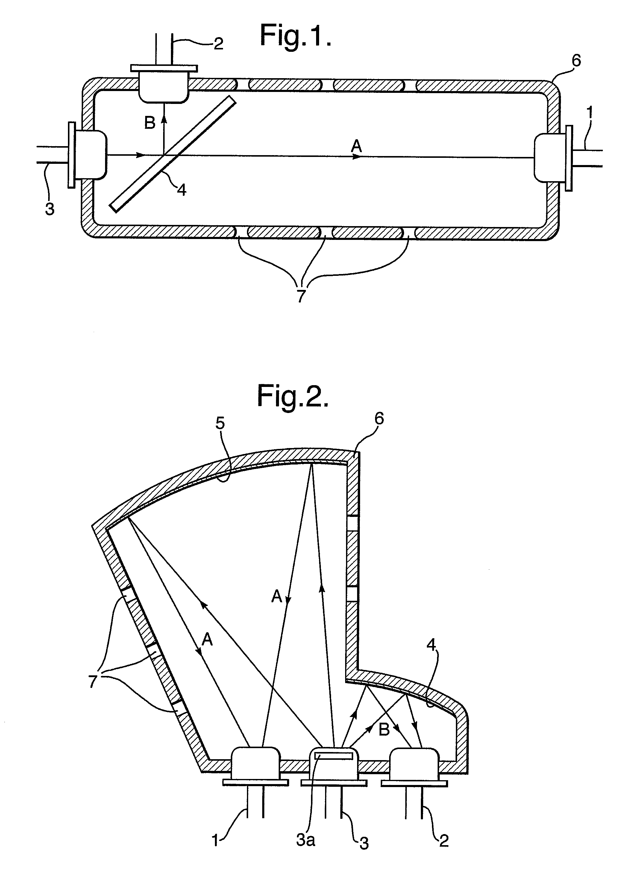
[0053]The first embodiment, shown in FIG. 1, implements a simple, linear design. An elongate chamber 6 is provided for containing a gas sample in use. In this example, the chamber 6 has a number of apertures 7 for gas ingress, which enables fluid communication between the interior of the chamber 6 and the surrounding atmosphere. A radiation source 3, in this case an InGaAs, PbS, or PbSe-based LED, is arranged at one end of the chamber 6 and is opposed by a first radiation detector 1, such as a photovoltaic detector, at the far end of the chamber 6. Radiation emitted by source 3 passes through the chamber 6 on a first optical path A to reach the first detector 1.

[0054]A light guiding assembly comprising a partially-reflective element in the form of semi-silvered mirror 4 is disposed between the radiation source 3 and the first detector 1 so as to intercept the radiation emitted by the source 3. Part of the radiation passes through the semi-silvered mirror 4 to continue on the first o...

second embodiment

[0066]A second embodiment, shown in FIG. 2 (components equivalent to those in FIG. 1 retain the same reference numerals), is much improved in this sense, because photodetectors 1 and 2 are disposed close to one another, and on the same surface of the chamber 6.

[0067]This compact, temperature-stable design uses a light guiding assembly in the form of reflective mirrors 4 and 5. The chamber 6 is shaped so as to support a first mirror 4 close to the radiation source 3. The mirror intercepts only a portion of the radiation emitted by the source 3 and reflects it towards a photodetector 2 along a short optical path B. Radiation not intercepted by the first mirror 4 crosses a wide portion of the chamber 6 where it is reflected by a second mirror 5 towards another detector 1 along a longer optical path A. The long optical path A constitutes the sensing channel, and the short optical path B represents the reference channel.

[0068]The mirror elements 4 and 5 may comprise mirrors affixed to th...

third embodiment

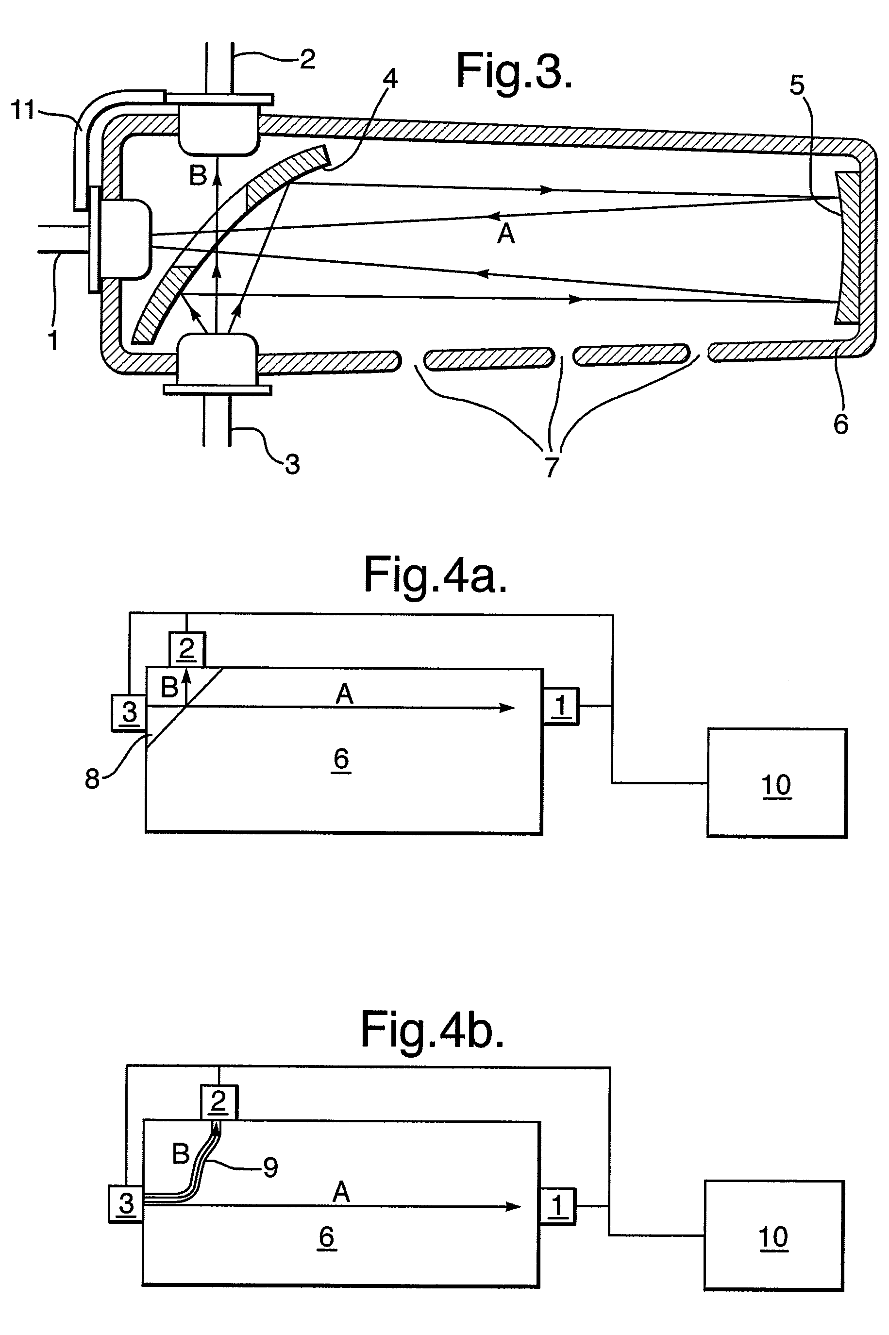
[0072]A third embodiment shown in FIG. 3, improves the temperature accuracy still further by the use of a thermal conductor 11 connecting the first and second detectors 1 and 2. In this way the photodetectors will have good thermal contact, leading them to remain in thermal equilibrium and maintain the same temperature as each other with a good accuracy.

[0073]The third embodiment makes use of a light guiding assembly comprising a partially reflective mirror 4 arranged adjacent the radiation source 3. As in the case of the second embodiment, the radiation source 3 may include a filter (not shown), such as a narrow bandwidth interference filter, adjusted to pass a radiation waveband corresponding to (at least including) an absorption line of the target gas. The reflected portion of the radiation is directed towards a mirror 5 arranged at the far end of the elongate chamber 6. The radiation is reflected back towards a first detector 1, passing through a transparent window in the partia...


PUM


Abstract

An optical absorption gas analyser for determining the concentration of a target gas in a sample is disclosed. The analyser comprises a chamber for containing the sample in use; a radiation source assembly arranged to emit radiation into the chamber; a first radiation detector assembly arranged to detect radiation transmitted along a first optical path through the chamber and a second radiation detector assembly arranged to detect radiation transmitted along a second optical path through the chamber, wherein the length of the second optical path which the sample can intercept is shorter than that of the first optical path. The analyser further comprises a processor adapted to generate a sensing signal SS based on the detected radiation transmitted along the first optical path and a reference signal SR based on the detected radiation transmitted along the second optical path. The processor determines the concentration of the target gas in the sample based on a comparison of the sensing signal with the reference signal.

Description

CROSS-REFERENCE TO RELATED APPLICATIONS[0001]None.TECHNICAL FIELD[0002]This invention relates to an improved instrument for the measurement of concentration of a target gas by means of optical absorption. In particular, the invention relates to apparatus and methods for non-dispersive infrared (NDIR) measurement based on the absorption of radiation by the gas of interest.BACKGROUND AND SUMMARY OF THE INVENTION[0003]Optical absorption techniques such as non-dispersive infrared (NDIR) measurement have been recognized for many years as sensitive, stable and reliable methods of gas concentration measurement. In a typical NDIR method, the selective absorption of infrared radiation by certain gas species of interest is measured to determine the concentration of the target gas in a sample. This has a wide variety of applications—for example, NDIR measurements detecting absorption of radiation by carbon dioxide and other gases, such as carbon monoxide or hydrocarbons, are commonly used to m...

Claims


Application Information

Patent Timeline
IPC IPC(8): G01N21/00
CPCG01N21/3504G01N2201/0668G01N2201/0662
Inventor TKACHUK, MICHAEL
Owner BAH HLDG
Why Eureka
Try Eureka