Ultrashort laser micro-texture printing

a laser microtexture and ultrashort technology, applied in the field of ultrashort laser microtexture printing, can solve the problems of limited utility of solid substrates such as metals, limited use of paper substrates, and limited use of conventional laser engraving, and achieve the effects of tighter focusing of incident laser beams, fast optical shutters, and rapid modulation of high-power femtosecond pulse trains

Inactive Publication Date: 2009-10-29
IMRA AMERICA
View PDF35 Cites 24 Cited by
  • Summary
  • Abstract
  • Description
  • Claims
  • Application Information

AI Technical Summary

Benefits of technology

[0009]Apparatus and methods are disclosed that utilize micro-structuring of materials and / or material surfaces for image engraving, where the micro-structures are produced with ultrafast pulse trains. In some embodiments, high-contrast and high-resolution grayscale images can be generated by variation of the accumulated laser fluence incident on a material surface. In one embodiment, laser irradiation conditions are varied in order to cause surface roughness variations, which may correspond to variations in light reflectance (e.g., diffraction and / or scattering) and / or light absorption. Light reflectance and / or absorption variations induced by surface micro-structuring provide for smooth variations of grayscales and enable production of images to be machined on the surface of a wide variety of materials.
[0084]In an aspect of the ninth embodiment, variation in the total amount of optical energy delivered to different regions of the surface is provided by varying a scan speed of the laser beam relative to the surface, thereby causing variations in overlap of the optical pulses.

Problems solved by technology

This method works very well for paper substrates but has limited utility for solid substrates such as metals.
However, conventional laser engraving is very sensitive to laser irradiation parameters.
Image processing and / or image formation via micro-texturing with longer pulse laser systems may not achieve some of the advantages provided with shorter pulse laser systems.
For example, the longer pulse duration associated with some conventional lasers (e.g., >250 ps), may not provide control of surface roughness and may cause significant melting effects, which tend to destroy the fine textures achievable with shorter pulses.
Surface texturing for image engraving may be more difficult to perform in some organic materials (such as textiles and polymers), because they may tend to burn when machined using ˜1 μm laser wavelengths even if femtosecond laser pulses are used.
In some implementations, after fabrication the fine structures associated with ultrashort pulse image engraving may be sensitive to contamination.
For example, oil deposited by finger prints may be detrimental to the image.
In some cases, contamination from finger prints, water deposits, dust, etc. can become lodged in the fine structures and may reduce the image quality.

Method used


Image

  • Ultrashort laser micro-texture printing
  • Ultrashort laser micro-texture printing
  • Ultrashort laser micro-texture printing

Examples


Embodiment Construction

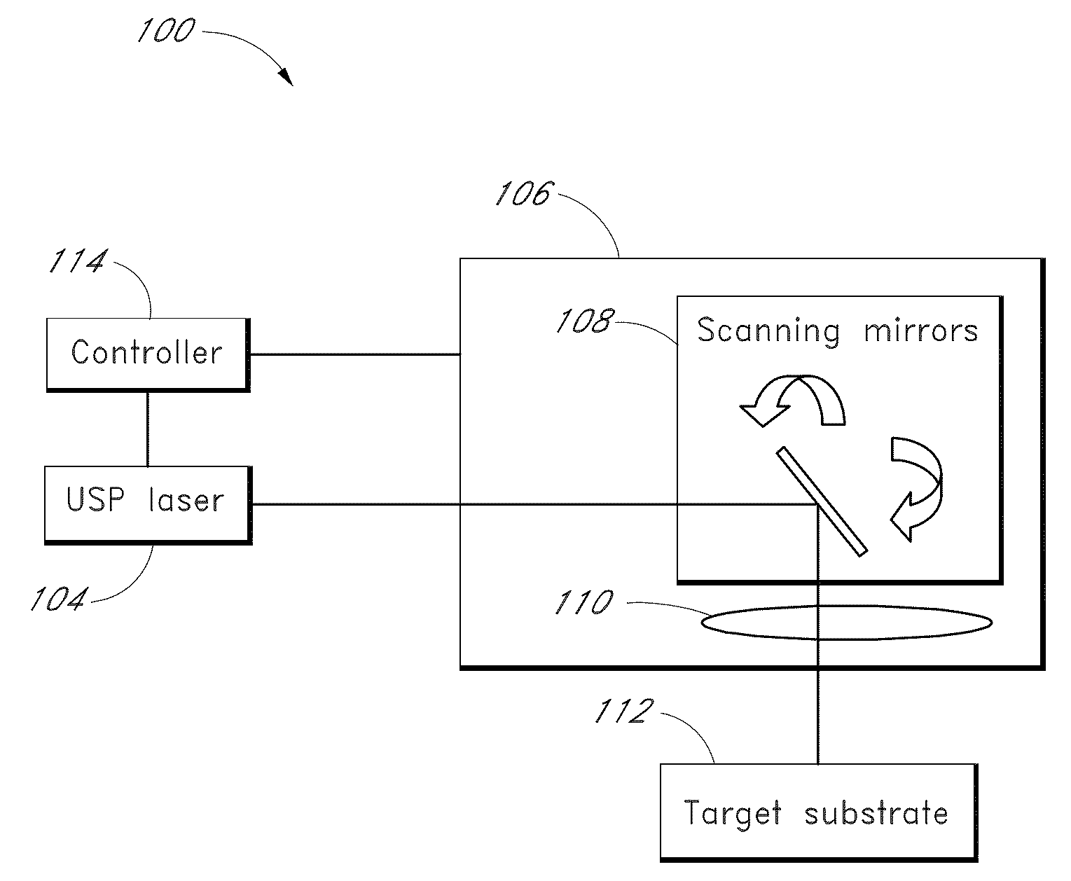
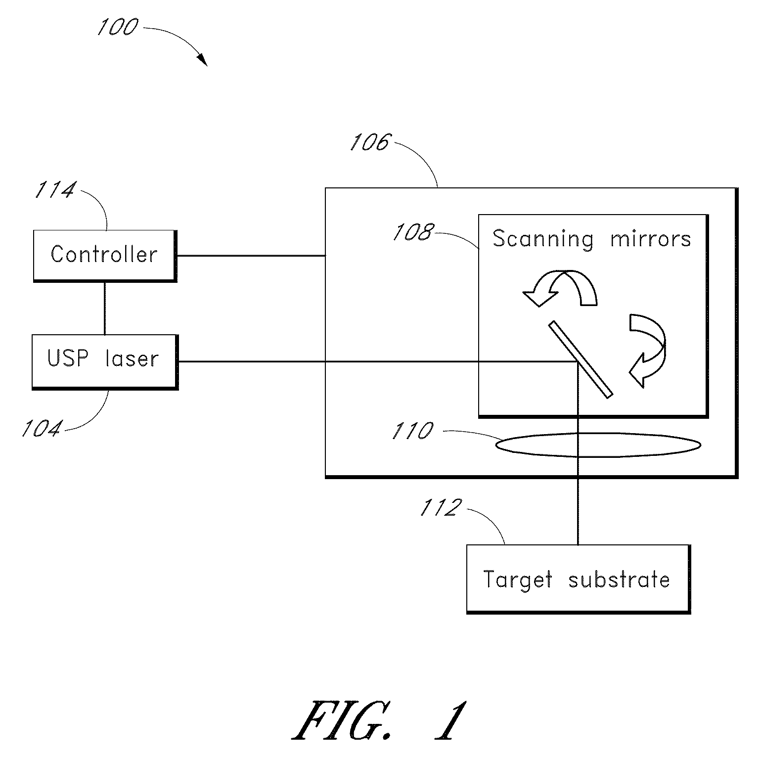
[0159]FIG. 1 schematically illustrates a first embodiment of a system 100 capable of use for image formation of a target substrate 112 via surface micro-structuring with ultrafast pulse trains. The system 100 comprises a laser system 104 and a scanning system 106. In this embodiment, the scanning system 106 includes two galvanometric scanning mirrors 108 capable of two-dimensional scanning. In other embodiments, a different number and / or type of scanning mirrors may be used. In some embodiments, the scanning may be one-dimensional. The scanning system 106 may also include focusing optics 110 such as, for example, an integrated F-theta lens capable of producing a substantially flat field of view at the target substrate 112. For example, in some embodiments, the F-theta lens is configured to produce a 20 μm laser focus spot with a substantially flat field of view over an area of about 8000 mm2. The scanning system 106 (and / or other system components) may be controlled by a controller ...


PUM

PropertyMeasurementUnit
energyaaaaaaaaaa
energyaaaaaaaaaa
wavelengthsaaaaaaaaaa

Abstract

Systems and methods for providing laser texturing of solid substrates are disclosed. The texturing may be used to provide grayscale images obtainable from substrates, which may include steel, aluminum, glass, and silicon. In some embodiments, images may be obtainable from the substrate by modifying the reflective, diffractive, and / or absorptive features of the substrate or the substrate surface by forming random, periodic, and / or semi-periodic micro-structure features on the substrate (or substrate surface) by an ultrafast laser pulse train. The ultrafast pulse train may be modulated in order to vary, for example, optical exposure time, pulse train intensity, laser polarization, laser wavelength, or a combination of the aforementioned. The ultrafast pulse train and the substrate may be scanned with respect to each other to provide different optical energies to different regions of the substrate (or substrate surface). In some embodiments, the image is provided by making one or more passes of the ultrafast laser pulse train relative to the substrate.

Description

CROSS-REFERENCE TO RELATED APPLICATIONS[0001]This application claims the benefit under 35 U.S.C. § 120 and 35 U.S.C. § 365(c) as a continuation of International Application PCT / US2008 / 051713 designating the United States, with an international filing date of Jan. 22, 2008, entitled “ULTRASHORT LASER MICRO-TEXTURE PRINTING,” which claims the benefit under 35 U.S.C. § 119(e) of U.S. Provisional Patent Application No. 60 / 886,285, filed Jan. 23, 2007, entitled “ULTRASHORT LASER MICRO-TEXTURE PRINTING,” each of the above-referenced applications is hereby expressly incorporated by reference herein in its entirety.BACKGROUND[0002]1. Field[0003]This disclosure relates to formation of textured regions on surfaces of materials by ultrashort optical pulses and to formation of images on materials. The disclosure also relates to techniques for optical modulation of ultrafast pulse trains.[0004]2. Description of Related Art[0005]In conventional ink printing, grayscales in images are generally cre...

Claims


Application Information

Patent Timeline
Patent Type & Authority Applications(United States)
IPC IPC(8): H04N1/04
CPCB41J2/442B41J2/471H04N1/407G06K15/129G06K15/1209H04N1/40037B23K26/352
Inventor SHAH, LAWRENCEFERMANN, MARTIN E.
Owner IMRA AMERICA
Why Eureka
Try Eureka