
Magnetic structure including two ferromagnetically coupled magnetic layers and method of manufacturing same

Active Publication Date: 2009-10-29
TDK CORPARATION
View PDF10 Cites 0 Cited by
  • Summary
  • Abstract
  • Description
  • Claims
  • Application Information

AI Technical Summary

Benefits of technology

[0022]According to the first magnetic structure, the second magnetic structure, and the methods of manufacturing the first magnetic structure and the second magnetic structure of the present invention, the nonmagnetic insulating layer contains an oxygen atom, the nonmagnetic adhesion layer is composed of one element or a plurality of elements selected from the group consisting of Al, Si and nonmagnetic transition metal elements except Ru, the bond enthalpy of a diatomic molecule composed of an atom of the one element or each of the plurality of elements and an oxygen atom is 400 kJ / mol or higher, and the nonmagnetic adhesion layer has a thickness within the range of 0.3 to 0.8 nm. This makes it possible to ensure adhesion of the nonmagnetic adhesion layer to the first magnetic layer and the nonmagnetic insulating layer, and also to establish ferromagnetic coupling between the first magnetic layer and the second magnetic layer.

Problems solved by technology

However, an electrode film made of a magnetic material is typically low in adhesion to a nonmagnetic insulating layer.
Consequently, if an electrode film of a magnetic material is formed on the first magnetic layer and the nonmagnetic insulating layer, the electrode film can peel off from the nonmagnetic insulating layer during processing for forming magnetic heads from the foregoing substructure, or cracking can occur in the electrode film due to thermal stress during a writing operation.
As a result, the write head suffers problems such as a reduction in write magnetic field and erroneous writing or erasure of data on the recording medium caused by the leakage flux.

Method used


Image

  • Magnetic structure including two ferromagnetically coupled magnetic layers and method of manufacturing same
  • Magnetic structure including two ferromagnetically coupled magnetic layers and method of manufacturing same
  • Magnetic structure including two ferromagnetically coupled magnetic layers and method of manufacturing same

Examples


Embodiment Construction

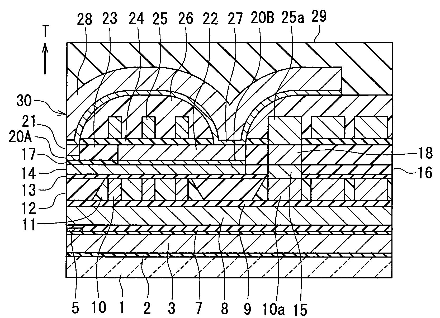
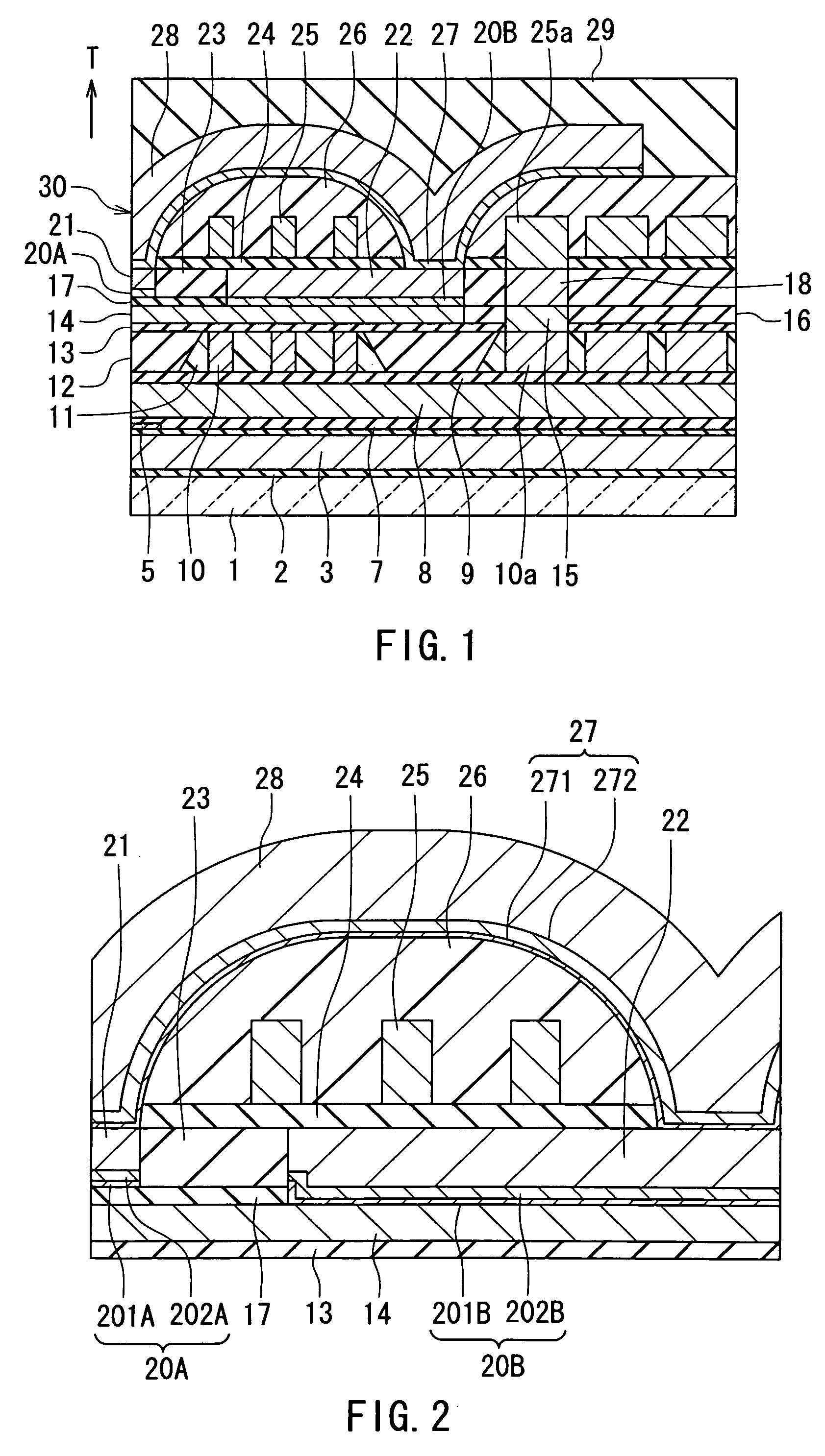
[0074]An embodiment of the present invention will now be described in detail with reference to the drawings. Reference is first made to FIG. 1 to describe the configuration of a magnetic head of this embodiment. Here is given an example of a magnetic head for the perpendicular magnetic recording system. FIG. 1 is a cross-sectional view showing the configuration of the magnetic head. FIG. 1 shows a cross section perpendicular to the medium facing surface and the top surface of the substrate. The arrow marked with T in FIG. 1 shows the direction of travel of a recording medium.

[0075]As shown in FIG. 1, the magnetic head of the present embodiment has a medium facing surface 30 that faces toward the recording medium. The magnetic head includes: a substrate 1 made of a ceramic material such as alumina-titanium carbide (Al2O3—TiC); an insulating layer 2 made of an insulating material such as alumina (Al2O3) and disposed on the substrate 1; a first read shield layer 3 made of a ferromagnet...


PUM

PropertyMeasurementUnit
Thicknessaaaaaaaaaa
Nanoscale particle sizeaaaaaaaaaa
Bond energyaaaaaaaaaa

Abstract

A magnetic structure includes a first magnetic layer, a nonmagnetic insulating layer, a nonmagnetic adhesion layer disposed on the top surfaces of the first magnetic layer and the nonmagnetic insulating layer, and a second magnetic layer disposed on the nonmagnetic adhesion layer. The nonmagnetic insulating layer contains an oxygen atom. The nonmagnetic adhesion layer is composed of one element or a plurality of elements selected from the group consisting of Al, Si and nonmagnetic transition metal elements except Ru, and the bond enthalpy of a diatomic molecule composed of an atom of the one element or each of the plurality of elements and an oxygen atom is 400 kJ / mol or higher. The nonmagnetic adhesion layer has a thickness within a range of 0.3 to 0.8 nm. The first magnetic layer and the second magnetic layer are ferromagnetically coupled to each other.

Description

BACKGROUND OF THE INVENTION[0001]1. Field of the Invention[0002]The present invention relates to a magnetic structure for use in, for example, a magnetic head of a magnetic read / write apparatus, the magnetic structure including two magnetic layers ferromagnetically coupled to each other, and to a method of manufacturing such a magnetic structure.[0003]2. Description of the Related Art[0004]Higher recording density is constantly required of a magnetic read / write apparatus such as a magnetic disk drive so as to achieve a higher storage capacity and smaller dimensions. Typically, a thin-film magnetic head for use in a magnetic read / write apparatus has a structure in which a read head having a magnetoresistive element (hereinafter also referred to as an MR element) for reading and a write head having an induction-type electromagnetic transducer for writing are stacked on a substrate. The induction-type electromagnetic transducer includes a coil that generates a magnetic field correspond...

Claims


Application Information

Patent Timeline
IPC IPC(8): G11B5/33
CPCG11B5/11G11B5/3146Y10T428/1171G11B5/3163G11B5/3967Y10T428/1193Y10T428/32G11B5/1278
Inventor MAKINO, KENZOSANO, MASASHIYAMAGUCHI, ATSUSHI
Owner TDK CORPARATION
Learn More