Three-phase buck-boost power factor correction circuit and controlling method thereof

Active Publication Date: 2009-10-29
DELTA ELECTRONICS INC
View PDF3 Cites 48 Cited by
  • Summary
  • Abstract
  • Description
  • Claims
  • Application Information

AI Technical Summary

Benefits of technology

[0010]It is therefore an object of the present invention to provide a three-phase buck-boost PFC circuit and a controlling method thereof, this circuit includes three independent single-phase three-level buck-boost PFC circuit, the first, the second and the third single-phase three-level buck-boost PFC circuits would not influence each other due to having a neutral line, operate independently from each other, could be used to improve the THD of the three-phase buck-boost PFC circuit and to increase the efficiency of the same. The

Problems solved by technology

The electrical power apparatuses are mostly going through the rectifiers and the electrical power network interfaces, a typical rectifier is a nonlinear circuit including diodes or thyristors, and the nonlinear circuit generates lots of current harmonics and reactive powers in the electrical power network, pollutes the electrical power network, and becomes a public nuisance of the electrical power.
This kind of circuit is only suitable for the condition of single-phase input, for certain occasions, we need to use the three-phase input voltage, and thus this kind of single-phase circuit could not fulfill the requirements of the system.
But it also has drawbacks: due to that the neutral point of the three-phase three-line configuration is formed by the three-phase AC input voltag

Method used


Image

  • Three-phase buck-boost power factor correction circuit and controlling method thereof
  • Three-phase buck-boost power factor correction circuit and controlling method thereof
  • Three-phase buck-boost power factor correction circuit and controlling method thereof

Examples


Embodiment Construction

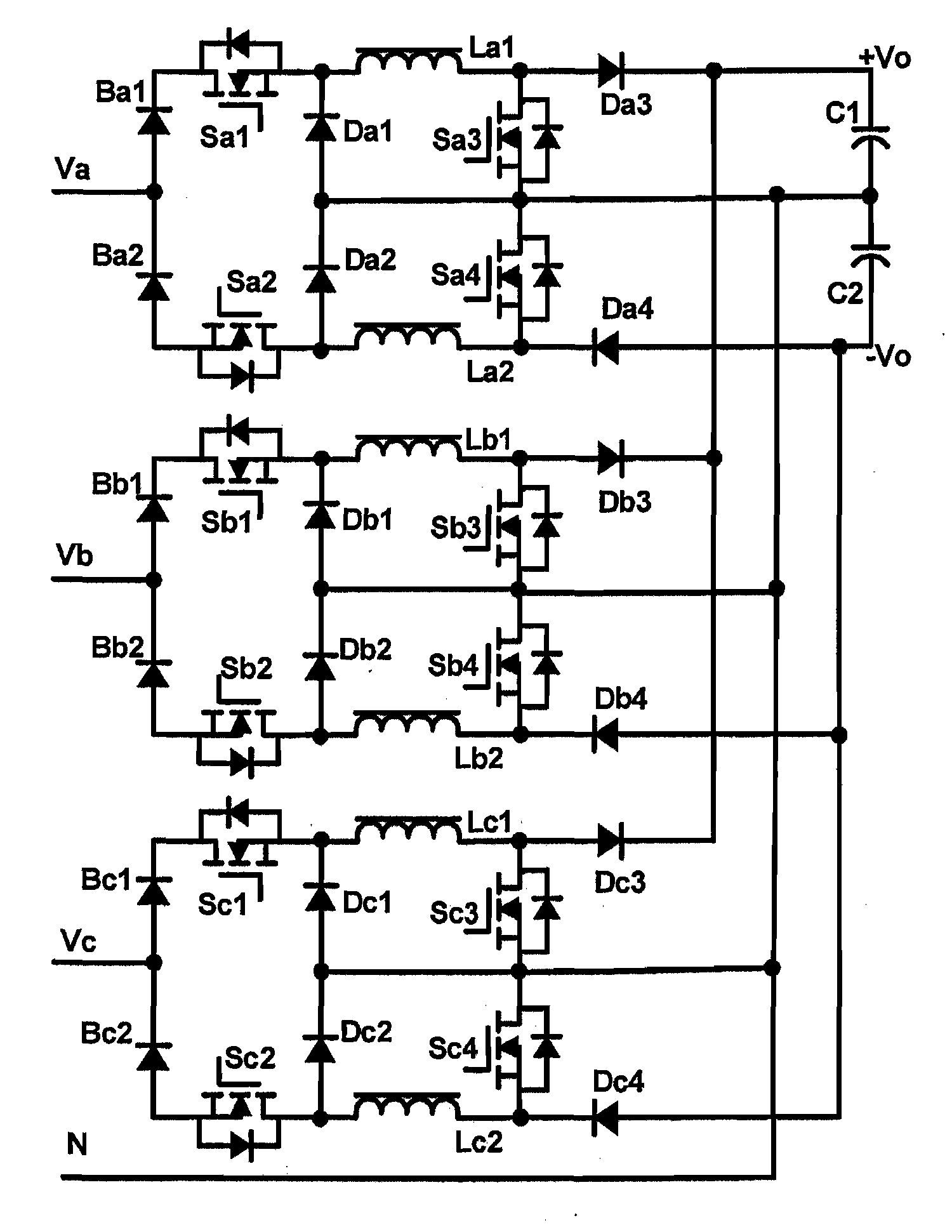
[0039]To overcome the drawbacks of the conventional three-phase three-line buck boost PFC circuit, the present invention proposed a three-phase four-line buck-boost PFC circuit (the input power source has a natural neutral point) employing three independent single-phase three-level buck-boost PFC circuits combined to control the three-phase input current as shown in FIG. 5. In which, it has diodes Ba1-Ba2, Bb1-Bb2, Bc1-Bc2, Da1-Da2, Db1-Db2, Dc1-Dc2, Da3-Da4, Db3-Db4 and Dc3-Dc4, switches Sa1-Sa4, Sb1-Sb4 and Sc1-Sc4, inductors La1-La2, Lb1-Lb2 and Lc1-Lc2, capacitors C1-C2 and a neutral line N causing the neutral point of the power source electrically connected to the neutral point of the PFC circuit, and the neutral point of the PFC circuit is the connecting node of the capacitors C1 and C2. And the three-phase four-line buck boost PFC circuit receives a three-phase input voltage having a first phase voltage Va, a second phase voltage Vb and a third phase voltage Vc and generates ...


PUM


Abstract

The configurations of a three-phase buck-boost power factor correction (PFC) circuit and a controlling method thereof are provided in the present invention. The proposed circuit includes a first single-phase buck-boost PFC circuit receiving a first phase voltage and having a first and a second output terminals and a neutral-point for outputting a first and a second output voltages, a second single-phase buck-boost PFC circuit receiving a second phase voltage and coupled to the first and the second output terminals and the neutral-point, a third single-phase buck-boost PFC circuit receiving a third phase voltage and coupled to the first and the second output terminals and the neutral-point, a first and a second output capacitors coupled to the first and the second output terminals respectively, and to the neutral-point also and a neutral line coupled to the neutral-point.

Description

FIELD OF THE INVENTION[0001]The present invention relates to a three-phase buck-boost power factor correction (PFC) circuit and a controlling method thereof. More particularly, it relates to a three-phase buck-boost PFC circuit employing three independent single-phase three-level buck-boost PFC circuits to improve the total harmonic distortion (THD) of the three-phase buck-boost PFC circuit and to increase the efficiency of the same.BACKGROUND OF THE INVENTION[0002]In the recent twenty years, the power electronic technology has obtained a quickly development, and has been widely applied to the fields of electrical power, chemical engineering and communications. The electrical power apparatuses are mostly going through the rectifiers and the electrical power network interfaces, a typical rectifier is a nonlinear circuit including diodes or thyristors, and the nonlinear circuit generates lots of current harmonics and reactive powers in the electrical power network, pollutes the electr...

Claims


Application Information

Patent Timeline
IPC IPC(8): H02M7/06
CPCH02M1/4216Y02B70/126H02M1/4225Y02B70/10Y02P80/10
Inventor TAN, JINGTAOLI, YANGZHOU, ZHIJIANYAN, SHICHAOTASI, WEN-YINYING, JIANPING
Owner DELTA ELECTRONICS INC
Why Eureka
Try Eureka