Damping systems for use in engines

a technology for damping systems and engines, applied in machines/engines, bearing units, liquid fuel engines, etc., can solve the problems of inadequate damping of the corresponding increase in engine vibration, and achieve the effect of improving the damping system

Active Publication Date: 2009-10-29
HONEYWELL INT INC
View PDF7 Cites 25 Cited by
  • Summary
  • Abstract
  • Description
  • Claims
  • Application Information

AI Technical Summary

Benefits of technology

[0006]The inventive subject matter provides an

Problems solved by technology

During engine operation when the rotor rotates, one or more of the components may be unbalanced which may cause vibration.
The damping systems may include isolators, shock absorbers, or other da

Method used


Image

  • Damping systems for use in engines
  • Damping systems for use in engines
  • Damping systems for use in engines

Examples


Embodiment Construction

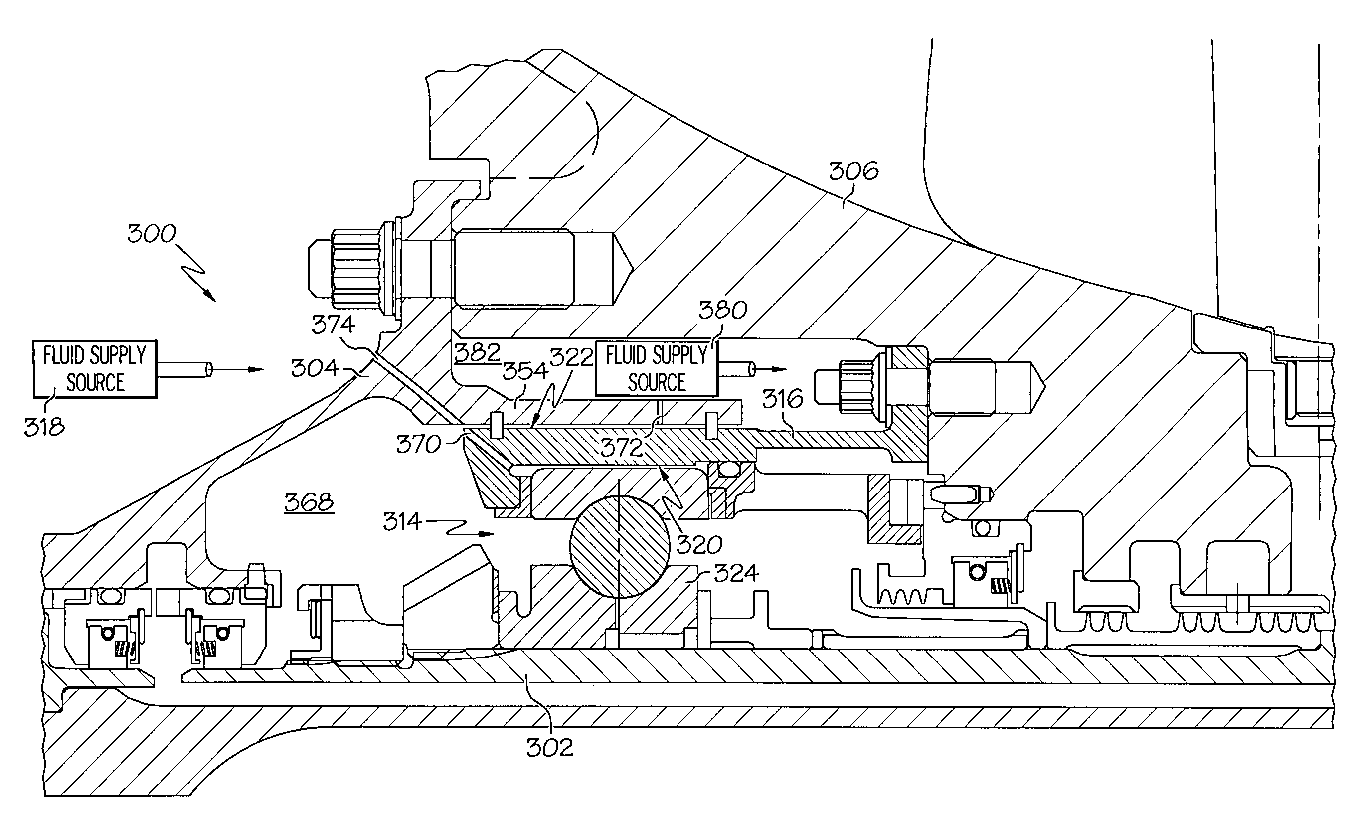
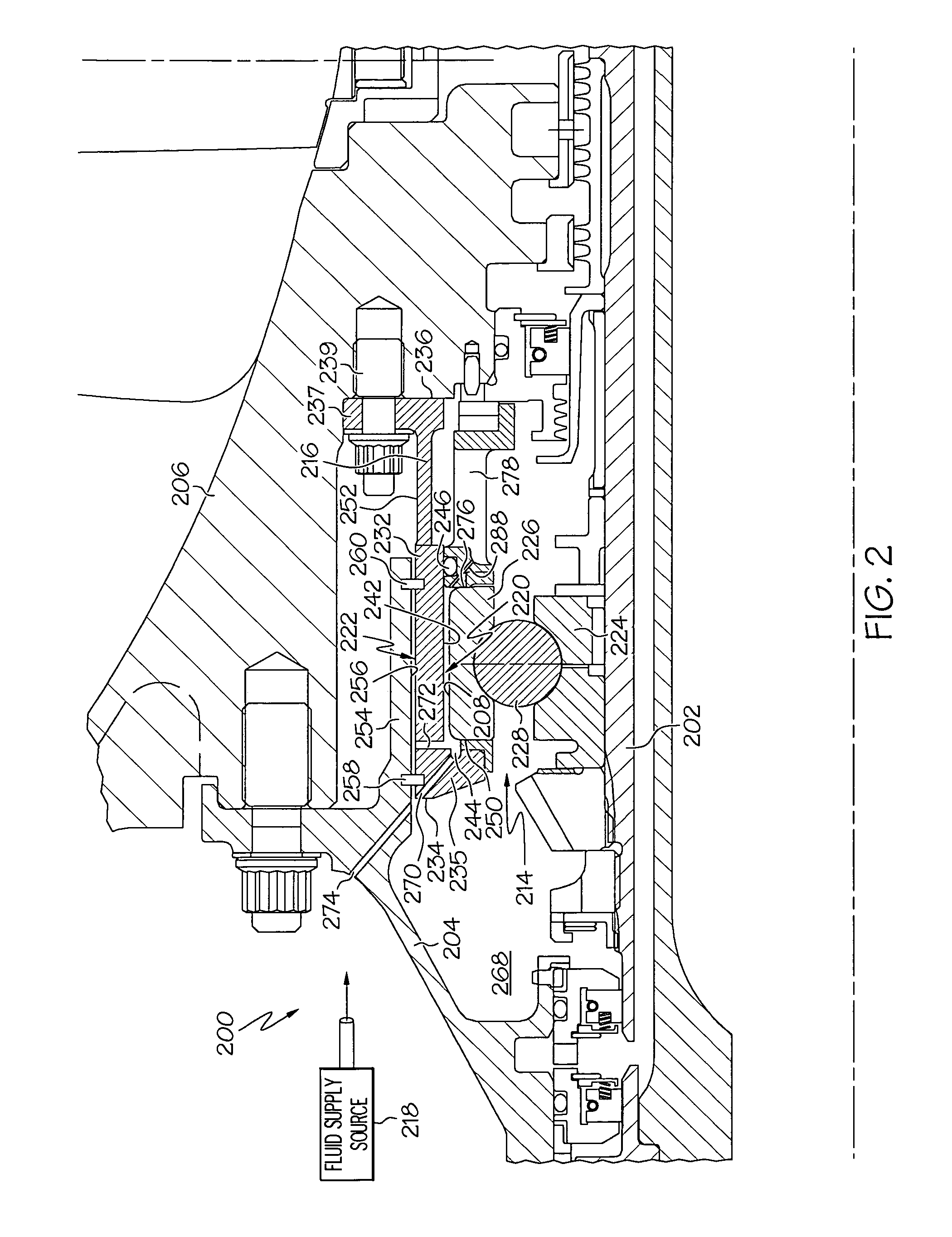
[0014]Before proceeding with the detailed description, it is to be appreciated that the described embodiments are not limited to use in conjunction with a particular type of turbine engine. Thus, although the present embodiments are, for convenience of explanation, depicted and described as being implemented in a multi-spool turbofan gas turbine jet engine, it will be appreciated that it can be implemented in various other types of turbine engine, and in various other systems and environments. Moreover, although the embodiments of the inventive subject matter are described as being implemented into a compressor section of the engine, it will be appreciated that the embodiments of the inventive subject matter may alternatively be used in any other section of the engine that may need vibration damping.

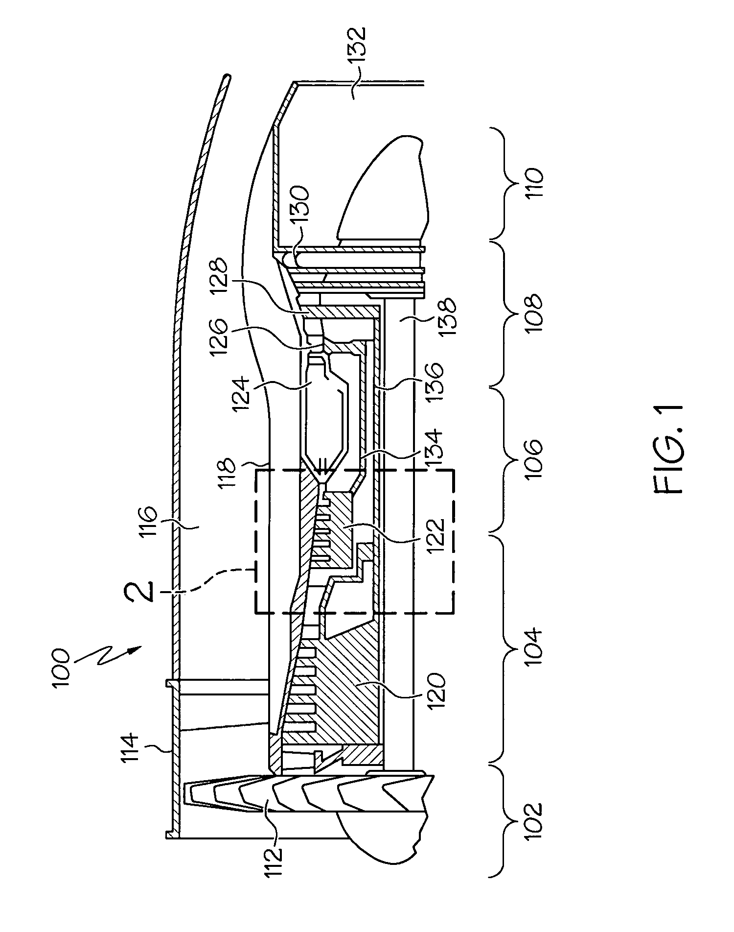
[0015]FIG. 1 is a simplified, schematic of a gas turbine engine 100, according to an embodiment. The gas turbine engine 100 generally includes an intake section 102, a compressor section...


PUM


Abstract

Damping systems and engines including the damping systems are provided. In one embodiment, and by way of example only, the damping system includes a rotor, a bearing assembly mounted to the rotor, a spring cage disposed around the bearing assembly, an axially-extending housing surrounding the spring cage, a first squeeze film damper formed between the bearing assembly and the spring cage, and a second squeeze film damper formed between the spring cage and the axially-extending housing.

Description

TECHNICAL FIELD[0001]The inventive subject matter relates to turbine engines for aircraft and, more particularly, to damping systems for use in a cold or hot section of the engine, such as, for example, in a compressor section.BACKGROUND[0002]A turbofan gas turbine engine may be used to power aircraft and may include, for example, a fan section, a compressor section, a combustor section, a turbine section, and an exhaust section, where each section has components that are mounted to a rotor. The fan section induces air from the surrounding environment into the engine and accelerates a fraction of the air toward the compressor section. The remaining fraction of air is accelerated into and through a bypass plenum, and out the exhaust section.[0003]The compressor section, which may include a high pressure compressor and a low pressure compressor, raises the pressure of the air it receives from the fan section to a relatively high level. The compressed air then enters the combustor sect...

Claims


Application Information

Patent Timeline
IPC IPC(8): F01D25/04
CPCY02T50/671F01D25/164F16C19/06F16C27/045F16C2360/23Y02T50/60
Inventor SPENCER, DOUGLASALAM, MOHSIULKINSINGER, GRIFF
Owner HONEYWELL INT INC
Why Eureka
Try Eureka