Fluid Purification Device and Fluid Purification Method
Inactive Publication Date: 2009-10-29
KITZ CORP
1 Cites 21 Cited by
AI-Extracted Technical Summary
Problems solved by technology
However, in the water purification device of Patent Document 1, the disinfection performance is tried to be improved by performing disinfection by the photocatalyst and the light source instead of disinfection which is performed merely by an ultraviolet lamp; however, this cannot be considered to have the disinfection performance capable of sufficiently disinfecting the water to be treated.
However, in this case, the water treatment device has the structure in which the ozone injection means is provided as another device in the upstream side of the reaction container, and ozone is separately generated by the outside ozone injection means; therefore, there has been a problem that the entire device becomes co...
Method used
[0061]The circulation pump 5 is arranged to pump up the water to be treated W of the bath 2 and circulate the water in the circulation piping 3. The filtration tank 6 is provided in the downstream side of the circulation pump 5 and is provided so as to be able to filtrate and remove fine foreign substances and the like which cannot be collected by the hair catcher 4. The heat exchanger 7 is provided in the downstream side of the filtration tank 6 so as to increase the temperature of the water to be treated W to a predetermined temperature.
[0062]Piping 3a generally has a negative pressure since it is a primary side of the pump, and piping 3b of the pump secondary side has a positive pressure. A branched pipe 3c which is branched from the part in front of the heat exchanger 7 at which the positive pressure is highest is connected to a mixing device (ejector) 14 and facilitates mixture of ozone and the fluid to be treated W.
[0067]In this case, as shown in FIG. 5, the gap of the space is most desirably within the range of about 0.6 to 1.5 mm, wherein the yield rate is increased even with respect to different voltages, and the generation amount of ozone, which will be described later, can be increased.
[0073]In the outer peripheral side of the outer tube 28, an ultraviolet light source 34 such as a fluorescent lamp which radiates ultraviolet light is disposed. The ultraviolet light source 34 is desired to contain a large amount of ultraviolet light (for example, having a wavelength of 410 nm or less) which causes the photocatalyst 32 of the titanium dioxide to efficiently generate positive holes and electrons, and the light source may be, for example, an ultraviolet lamp, a low-pressure/high-pressure mercury lamp, or a fluorescent lamp having a wavelength of 300 to 400 nm. Furthermore, the light source may be an array of a plurality of LEDs which radiate ultraviolet light. When LED lamps are used, the life can be extended, and miniaturization can be also enabled. Furthermore, since the calorific value can be also suppressed, more efficient purification of a fluid can be performed.
[0074]When the ultraviolet light source 34 is formed to have any of various shapes such as a linear (straight) shape, a cylindrical (circular) shape, a spiral shape, and a wave shape, the photocatalyst 32 can be caused to function more effectively. Furthermore, the ultraviolet light source 34 of the present embodiment is an electrodeless discharge tube which can perform discharge without electrodes; therefore, the electrodeless discharge tube 34 is caused to be adjacent to the electrode 30 upon discharge in ozone generation so that it is provided to be able to emit light without electrodes. In order to light the electrodeless discharge tube 34 brightly, the electrode 30 of a high frequency is preferred to be used at a high voltage. Furthermore, other than the electrodeless discharge tube, the ultraviolet light source 34 may use that of a type in which normal electrodes are provided to emit light.
[0075]In the further outer peripheral side of the outer tube 28, a protection tube 35 having an insulation property is provided, thereby forming heat insulation space S1 between the outer tube 28 and the protection tube 35, and the ultraviolet light source 34 is housed in the heat insulation space S1. In order to effectively radiate the discharge light by the ultraviolet light source 34 and the electrode 30, unshown aluminum or the like may be pasted on the inner surface side of the protection tube 35 by a means such as vapor deposition; and, in this case, since ultraviolet light and the like can be reflected, radiation can be performed at high efficiency.
[0076]The inner tube 27, the outer tube 28, and the protection tube 35 are integrated by attachment tubes 36 and 37, and O-rings 38 and 39 made of, for example, EPDM (ternary copolymer of ethylene, propylene, and diene mono...
Benefits of technology
[0033]According to the invention according to claim 6, the fluid purification device capable of effectively generating ozone from the oxygen or air flowing between the outer tube and the inner tube can be provided; furthermore, according to the invention according to claim 7, the fluid purification device capable of more effectively generating ozone by preventing dew condensation of the oxygen or air and utilizing the fed oxygen or air without waste can be provided.
[0034]According to the invention according to claim 8, mixed matters such as hair or garbage mixed in the fluid to be treated can be removed, and the entirety can be compactified. When the fluid purification device is to be replaced, it can be performed merely by detaching the device main body from the tubular body, and the working space required for replacement can be reduced.
[0035]According to the invention according to claim 9, the fluid purification method is capable exerting high disinfection/purification functions by generating a large amount of ozone and effectively mixing it with the fluid to be treated by a simple structure; and, when the fluid to be treated is liquid, the fluid purification method is capable of exerting the disinfection/...
Abstract
A fluid purification device capable of exerting high disinfection/purification functions by a simple structure is provided, and a fluid purification device capable of suppressing, for example, generation of noise and high-voltage charging upon disinfection/purification of a fluid to be treated composed of liquid such as water is provided.
This is a fluid purification device, wherein an inner tube composed of a non-conductive material and an outer tube which is spaced apart from the inner tube by predetermined space S and composed of a non-conductive material are concentrically provided, and a conductive member is attached to a part or entire periphery of the inside of the outer tube to provide an electrode so as to form a device main body; and the fluid purification device has a liquid purification function which, when a voltage is applied to the electrode of the device main body, performs discharge in the space S by using a fluid to be treated W composed of liquid such as water which flows within the inner tube as an earth electrode so as to cause a gas such as oxygen or air flowing in the space S to be reacted to generate ozone and mixes the ozone with the fluid to be treated W so as to purify the fluid.
Application Domain
DeodrantsWater/sewage treatment using germicide/oligodynamic-process +16
Technology Topic
Product gasEngineering +6
Image
Examples
- Experimental program(1)
Example
[0046] 10 DEVICE MAIN BODY [0047] 15 COMPRESSOR (DEVICE) [0048] 16 FLUID CONTROLLING DEVICE [0049] 17 AIR DRYER [0050] 27 INNER TUBE [0051] 28 OUTER TUBE [0052] 30 ELECTRODE [0053] 32 PHOTOCATALYST [0054] 34 ULTRAVIOLET LIGHT SOURCE [0055] S SPACE [0056] W FLUILD TO BE TREATED
BEST MODE FOR CARRYING OUT THE INVENTION
[0057]An example of a fluid purification device and a fluid purification method in the present invention will be described in detail based on an embodiment.
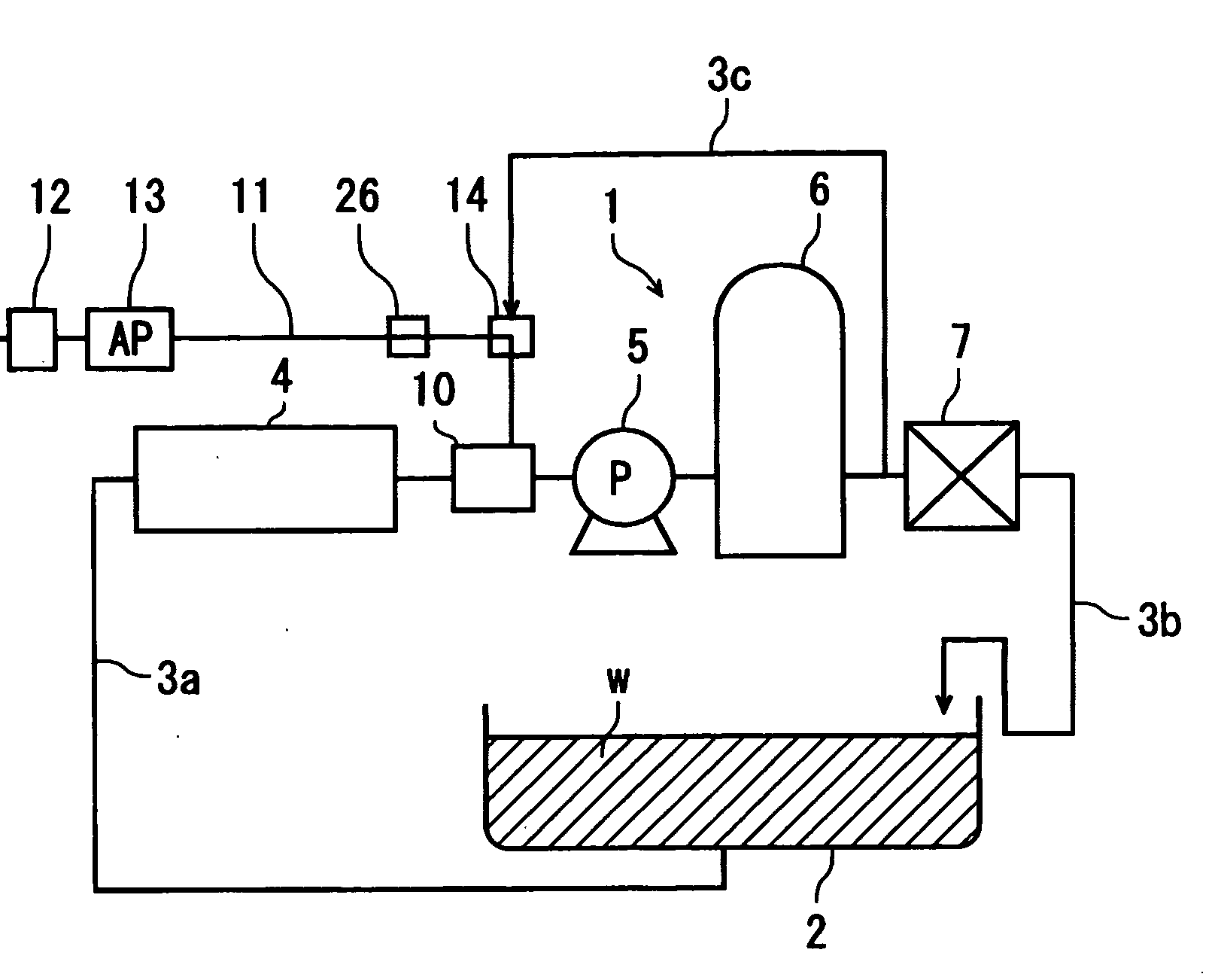
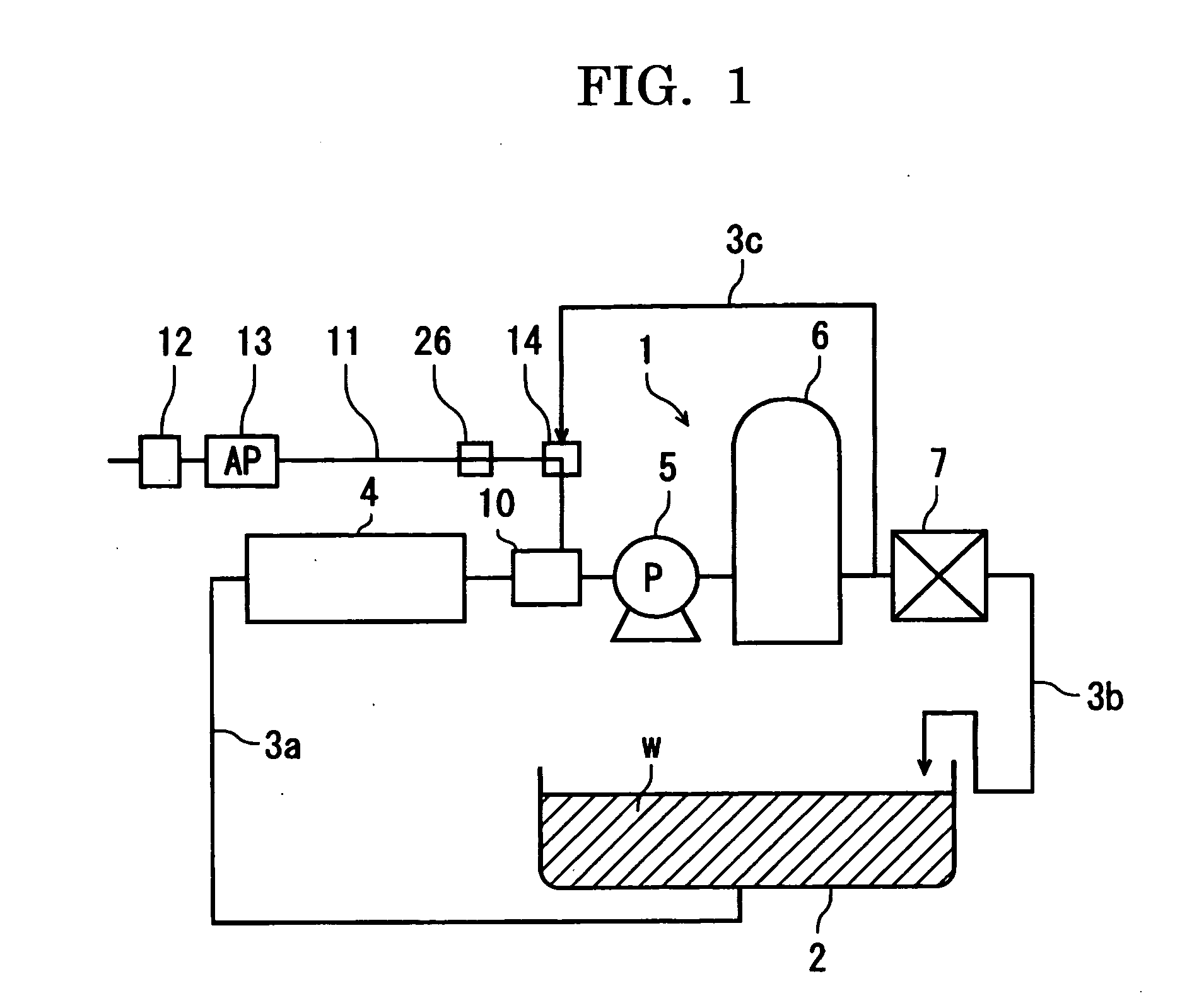
[0058]In FIG. 1, a schematic diagram of a fluid purification system utilizing a fluid purification device of the present invention is shown, wherein the fluid purification system 1 treats liquid such as water as a fluid to be treated, is utilized in a hot spring, health facility and the like in the present embodiment, and treats circulating hot water of a bath as a fluid to be treated (water to be treated) W.
[0059]In the fluid purification system 1, the water to be treated W is retained in a bath 2, and the water W to be treated is arranged to be circulated by connecting a hair catcher 4, a device main body 10 of the fluid purification device, a circulation pump 5, a filtration tank 6, and a heat exchanger 7 by circulation piping 3.
[0060]The hair catcher 4 is provided in front of the device main body 10 so as to collect comparatively large contaminants such as hair, garbage and the like mixed in the water to be treated W of the bath 2. Tubular bodies 21 and 22, which will be described later, are attached to the device main body 10, and, among these, at least in the tubular body 21 of the upstream side, at least the hair catcher 4 is attachably/detachably incorporated.
[0061]The circulation pump 5 is arranged to pump up the water to be treated W of the bath 2 and circulate the water in the circulation piping 3. The filtration tank 6 is provided in the downstream side of the circulation pump 5 and is provided so as to be able to filtrate and remove fine foreign substances and the like which cannot be collected by the hair catcher 4. The heat exchanger 7 is provided in the downstream side of the filtration tank 6 so as to increase the temperature of the water to be treated W to a predetermined temperature.
[0062]Piping 3a generally has a negative pressure since it is a primary side of the pump, and piping 3b of the pump secondary side has a positive pressure. A branched pipe 3c which is branched from the part in front of the heat exchanger 7 at which the positive pressure is highest is connected to a mixing device (ejector) 14 and facilitates mixture of ozone and the fluid to be treated W.
[0063]Separately from the circulation piping 3, air piping 11 is connected to the device main body 10; and a filter 12, an air pump 13, and an ejector 14 are provided on the air piping 11. The filter 12 removes foreign substances such as dust mixed in a gas such as oxygen or air sucked by the air pump 13, and they are provided so that the gas can be supplied to the device main body 10 by the air pump 13 via the air piping 11 and the ejector 14.
[0064]The ejector 14 is attached at a part in front of the device main body 10 and is formed to have a ring-like shape, which is not shown, by using a ceramic or a metal as the material. By virtue of this, the gas from the air pump 13 is mixed with the fluid from the branched pipe 3c, thereby causing it to be like fine bubbles and discharging them to the device main body 10 side.
[0065]In FIGS. 2 and 3, the device main body 10 is formed by combining a case main body 20, tubular bodies 21 and 22 which serve as a channel of the fluid to be treated W and has upstream/downstream sides, a high-voltage power supply 24, and an ozone supply channel 25, and this is combined with a check valve 26 and the above described ejector 14.
[0066]Within the case main body 20, as shown in FIG. 3, an inner tube 27 having, in the inner side thereof, a fluid channel 29 through which the water to be treated W flows and an outer tube 28 spaced apart from the inner tube 27 by predetermined space S are provided. The gap of the space S of the inner tube 27 and the outer tube 28 is, for example, a gap of about 0.5 to 2 mm, and, since the inner tube 27 and the outer tube 28 are concentrically provided, the gap becomes uniform in the circumferential direction.
[0067]In this case, as shown in FIG. 5, the gap of the space is most desirably within the range of about 0.6 to 1.5 mm, wherein the yield rate is increased even with respect to different voltages, and the generation amount of ozone, which will be described later, can be increased.
[0068]The inner tube 27 and the outer tube 28 are formed of a non-conductive material and, for example, are formed of a transparent or semi-transparent glass material which allows transmission of ultraviolet rays. The glass material is desired to be a material which readily allows transmission of ultraviolet rays such as quartz glass, borosilicic acid glass and the like; particularly, borosilicic acid glass and high silicic acid glass are comparatively inexpensive, and normal materials thereof can be used without modification; however, when the points of ultraviolet-ray transmittance, thermal resistance, strength and the like are taken into consideration, quartz glass is most preferable.
[0069]A conductive material is provided on the inside of the outer tube 28 so as to be an electrode 30 which is for high-voltage charging, and the electrode 30 is connected to the unshown positive side of the high-voltage power supply 24 which is provided outside of the outer tube 28. When a voltage is applied to the electrode 30 by the high-voltage power supply 24, the outer tube 28 is charged so as to be able to perform discharge to the inner tube 27 side. The electrode 30 is merely required to have a simple belt-like shape. In the present embodiment, the electrode is formed to have an approximately C-shape in a cross section and is provided to have a width of about 10 to 50 mm along an inner peripheral surface 28a of the outer tube 28 at a part of the inner peripheral surface 28a in the circumferential direction. However, the electrode 30 may be provided over approximately circularly (entire circumference) along the inner peripheral surface 28a.
[0070]The material of the electrode 30 is, for example, stainless steel, and the material formed like a thin film is used; however, other than this, a thin film strong against both discharge and ozone can be formed by attaching nickel chrome by vacuum vapor deposition. As other materials, for example, aluminum, copper, or titanium can be used; however, when aluminum or copper is used, surface treatment such as coating has to be performed for resistance against ozone. However, when the moisture content rate of air or oxygen is low, it can be used without a problem.
[0071]Within the inner tube 27, a large-surface-area material 31 made of titanium or a titanium alloy which comprises, for example, nets or titanium wires, an aggregate of fibrous titanium materials, or another porous titanium material is housed. On the large-surface-area material 31, a photocatalyst 32 of titanium dioxide may be formed on a first surface thereof in advance; alternatively, as is described later, the photocatalyst 32 of titanium dioxide may be formed during usage by generated ozone.
[0072]When the large-surface-area material 31 is finely formed, the reactivity with ozone is increased, and the photocatalyst 32 can be reliably formed. The large-surface-area material 31 may be formed by a material other than titanium and the titanium alloy, and, for example, a material such as glass, stainless steel, silica gel and the like can be used as the large-surface-area material.
[0073]In the outer peripheral side of the outer tube 28, an ultraviolet light source 34 such as a fluorescent lamp which radiates ultraviolet light is disposed. The ultraviolet light source 34 is desired to contain a large amount of ultraviolet light (for example, having a wavelength of 410 nm or less) which causes the photocatalyst 32 of the titanium dioxide to efficiently generate positive holes and electrons, and the light source may be, for example, an ultraviolet lamp, a low-pressure/high-pressure mercury lamp, or a fluorescent lamp having a wavelength of 300 to 400 nm. Furthermore, the light source may be an array of a plurality of LEDs which radiate ultraviolet light. When LED lamps are used, the life can be extended, and miniaturization can be also enabled. Furthermore, since the calorific value can be also suppressed, more efficient purification of a fluid can be performed.
[0074]When the ultraviolet light source 34 is formed to have any of various shapes such as a linear (straight) shape, a cylindrical (circular) shape, a spiral shape, and a wave shape, the photocatalyst 32 can be caused to function more effectively. Furthermore, the ultraviolet light source 34 of the present embodiment is an electrodeless discharge tube which can perform discharge without electrodes; therefore, the electrodeless discharge tube 34 is caused to be adjacent to the electrode 30 upon discharge in ozone generation so that it is provided to be able to emit light without electrodes. In order to light the electrodeless discharge tube 34 brightly, the electrode 30 of a high frequency is preferred to be used at a high voltage. Furthermore, other than the electrodeless discharge tube, the ultraviolet light source 34 may use that of a type in which normal electrodes are provided to emit light.
[0075]In the further outer peripheral side of the outer tube 28, a protection tube 35 having an insulation property is provided, thereby forming heat insulation space S1 between the outer tube 28 and the protection tube 35, and the ultraviolet light source 34 is housed in the heat insulation space S1. In order to effectively radiate the discharge light by the ultraviolet light source 34 and the electrode 30, unshown aluminum or the like may be pasted on the inner surface side of the protection tube 35 by a means such as vapor deposition; and, in this case, since ultraviolet light and the like can be reflected, radiation can be performed at high efficiency.
[0076]The inner tube 27, the outer tube 28, and the protection tube 35 are integrated by attachment tubes 36 and 37, and O-rings 38 and 39 made of, for example, EPDM (ternary copolymer of ethylene, propylene, and diene monomer for cross linking) are attached between the inner tube 27 and the outer tube 28 and the attachment tubes 36 and 37; thus, leakage of ozone and the water to be treated W to outside is eliminated, and the attachment tubes 36 and 37 can be readily detached upon disassembly in maintenance or the like.
[0077]After the attachment tubes 36 and 37 are combined, air channel 36b and 37b formed in the attachment tubes 36 and 37 are communicated with the space S; and, when a gas such as air or oxygen is introduced from an inlet 37a provided in the attachment tube 37, the gas passes through the space S through the air channel 36b and then can be discharged from an outlet 36a through an air channel 36b in the attachment tube 36. The check valve 26 is provided at an intermediate position of the ozone supply channel 25 connected to the outlet 36a; therefore, the ozone discharged from the outlet 36a goes through the check valve 26, the flow rate of the fluid from the branched pipe 3c is increased by an unshown narrow path within the ejector 14, and it is supplied in a mixed state from the tubular body 21.
[0078]An ozone supply opening 21b is communicated with a fluid channel 29 and is provided so that ozone can be mixed with the water to be treated W flowing through the fluid channel 29.
[0079]The tubular bodies 21 and 22 having an inflow opening 21a and an outflow opening 22a are connected to the attachment tubes 36 and 37; thus, the water to be treated W that flows in from the inflow opening 21a passes through the fluid channel 29, mixed with ozone, and then flows out from the outflow opening 22a.
[0080]Subsequently, operation of the above described embodiment of the fluid purification device in the present invention will be described. The water to be treated W is pressurized by the circulation pump 5, fed into the filtration tank 6 with a pressure, wherein foreign substances and the like are removed, then heated to a certain temperature via the heat exchanger 7, and returned into the bath 2. In the upstream side of the circulation pump 5, the water to be treated W from the bath 2 sucked by the circulation pump 5 flows into the device main body 10 after hair and the like is removed by the hair catcher 4.
[0081]Meanwhile, when a gas is introduced from the inlet 37a of the device main body 10 by the air piping 11, the gas is introduced into the space S through the air channel 37b.
[0082]At this point, when the electrode 30 provided on the outer tube 28 is positively charged by the high-voltage power supply 24, the water to be treated W flowing through the fluid channel 29 of the inner tube 27 serves as an earth electrode and is negatively charged, and discharge is performed from the electrode 30 toward the earth electrode (water to be treated W). The electrode 30 has a belt-like shape, and the water to be treated W is liquid; therefore, this discharge becomes silent discharge, and ozone is generated when the gas passes through this discharge section.
[0083]The generated ozone passes through the air channel 36b, is discharged from the outlet 36a, supplied in the state of fine bubbles from the ozone supply opening 21b via the check valve 26 and the ejector 14 in the upstream side of the water to be treated W, and is mixed with the water to be treated W from the upstream side of the fluid channel 29. As a result, a purification treat of the water to be treated W by the ozone can be performed.
[0084]The water to be treated W mixed with the ozone passes through the gaps of the large-surface-area material 31, and ultraviolet light is generated upon discharge of the electrode 30. When this ultraviolet light irradiates the photocatalyst 32 of the large-surface-area material 31, the disinfection/purification function by the photocatalyst 32 works in the manner described below, thereby simultaneously performing treatment of the water to be treated W.
[0085]Then, since the inner tube 27 and the outer tube 28 are formed of a transparent or semi-transparent glass material, the ultraviolet light from the ultraviolet light source 34 can irradiate the photocatalyst 32 at high efficiency, and the function of the photocatalyst 32 is improved.
[0086]Even when the photocatalyst 32 on the surface of the large-surface-area material 31 is exfoliated, the ozone in the water to be treated W undergoes oxidation reaction with the exposed titanium atoms, so that the photocatalyst 32 comprising titanium dioxide can be always generated on the surface of the large-surface-area material 31.
[0087]The principles of the disinfection/purification action using the photocatalyst 32 will be described. When the photocatalyst 32 such as titanium dioxide which is a semiconductor substance is irradiated with ultraviolet light having a wavelength of 400 nm or less, positive holes are generated in the valence band, and electrons are generated in the conductive band. The oxidation potential of the positive holes are lower than the oxidation potentials of fluorine, ozone, hydrogen peroxide and the like, organic matters are completely oxidized and decomposed by the photocatalyst 32 and finally completely oxidized into a carbon dioxide gas and water, a sulfuric acid, a nitric acid and the like. In the mechanism of the oxidation reaction by the photocatalyst 32, oxidation reactions are considered to be caused by the positive holes, which are generated when the photocatalyst 32 is irradiated with ultraviolet light, or hydrooxyl radicals (OH radicals), which are generated by the reaction between the positive holes and water and have extremely excellent reaction activity. At this point, the reduction reaction between the electrons, which are generated at the same time as the positive holes generated when the ultraviolet light is irradiated, and an oxide gas and the like progresses in parallel. The action of the photocatalyst 32 has the disinfection performance that is stronger than conventional disinfection agents such as ozone, hydrogenperoxide, chlorine and the like and also has decomposition performance of the organic matters. Moreover, since the life of the positive holes or OH radicals generated by the light irradiation is a millisecond or less, which is short, there is no remainder after treatment like the oxidizing agents such as ozone and hydrogen peroxide, and there is an advantage that the device that treats the remaining oxidizing agent is not required. Therefore, the water to be treated W can be effectively purified by using the photocatalyst 32.
[0088]Ozone has strong disinfection power and has extremely high purifying power. In addition, since it can decompose organic matters, it has large effects on purification of circulating water, purification of water supply and sewerage, disinfection and the like. However, a certain type of oxides and organic matters include the substances which are not reacted with ozone, and some of the circulating water of hot springs and the like cannot be treated depending on the spring quality. In this case, almost all the spring quality can be treated by combining ozone with the photocatalyst 32.
[0089]As shown in FIG. 6, a device 15 such as a compressor (compression device) may be provided in the upstream side of the device main body 10; and, specifically, a fluid purification system 40 may be configured so that, subsequent to the compressor 15, the filter 12 and, in addition to that, a fluid controller 16 are provided in the air piping 11.
[0090]In the fluid purification system 40, air is pressurized by the compressor 15 to about 0.2 to 1 MPa and then fed to the fluid controller 16, flow control adjustment to 1 to 20 L/min is performed by the fluid controller 16, and the air is caused to flow through the space S between the inner tube 27 and the outer tube 28; thus, compared with the case in which merely suction by a normal air pump and ejector is performed, the generation amount of ozone that is about 1.3 to 1.5 times larger can be obtained.
[0091]As shown in FIG. 7, a fluid purification system 41 may be configured so that, subsequent to the device 15 such as a compressor, the filter 12, an air dryer 17, and the fluid controller 16 are provided in the air piping 11. In the fluid purification system 41, air is pressurized by the compressor 15 to about 0.2 to 1 MPa, then goes through the air dryer 17, then is fed to the fluid controller 16, and is subjected to flow control adjustment by the fluid controller 16 to 1 to 20 L/min; and the air is caused to flow through the space S. In this manner, the air for generating ozone is desired to be dry air, and the generation amount of ozone is significantly increased when the air compressed by the compressor is used in generation of ozone, and, furthermore, when dry air is used.
[0092]In the graph of FIG. 4, the relation between the voltage and the ozone generation amount at an air flow rate of 5 L/min is shown. According to this graph, there is a difference of about 2.4 times between the ozone generation amount of the case using merely the air pump 13 and the generation amount of ozone of the case of FIG. 7 in which the compressor 15 and the air dryer 17 are combined. Even in the case of FIG. 6 in which the compressor 15 is used, the effect of 1. 4 times can be recognized (at 80 V) when compared with the cause using the air pump.
[0093]These are the effects of the case in which the pressure of the used compressor 15 is 0.5 MPa as a condition of the graph of FIG. 4, and the generation amount can be increased when the pressure is increased.
[0094]Instead of the air dryer 17, the air may be dried by using an unshown drying agent such as silica gel or a freezing-type dryer, and, also in this case, equivalent effects as the case using the air dryer 17 can be obtained.
[0095]Furthermore, generation of ozone can be increased by using an unshown oxygen tank or oxygen generator (generally, PSA device).
[0096]Since the ultraviolet light is generated in the above described manner upon discharge, disinfection can be also performed when the ultraviolet light directly irradiates the water to be treated W; moreover, since the inner tube 27 and the outer tube 28 are formed of a glass material as described above, the transmittance of the ultraviolet light is increased, and the irradiation amount of the ultraviolet light with respect to the water to be treated W is increased, thereby enhancing the disinfection power. Moreover, the photocatalyst can be also activated by the discharged light.
[0097]In addition, since the ultraviolet light source 34 is separately provided the outside of the outer tube 28, the water to be treated W can be also disinfected/purified by the strong ultraviolet light from the ultraviolet light source 34, wherein the purification effects are further enhanced.
[0098]As described above, the fluid purification system 1 can generate high-concentration ozone by effectively changing oxygen into ozone and has the liquid purification function which mixes the ozone with the water to be treated W and performs purification. Furthermore, when disinfection of the water to be treated W or decomposition treatment of the organic matters and purification is performed by the photocatalyst 32 and the ultraviolet rays, a purification treat can be effectively performed.
[0099]For example, when air is a raw material, the ozone generation amount of up to 3g/h can be obtained; therefore, a bath of about 20 to 60 t can be handled as the bath equipped with the fluid purification system. Herein, contamination by Legionella about to be generated in the bath can be reliably prevented.
[0100]Furthermore, when oxygen is a raw material, an ozone generation amount of about 15 g/h is obtained, and a bath of up to about 300 t can be handled.
[0101]In the fluid purification method, various fluids other than the hot water of the bath 2 can be used as the object of the water to be treated W, and, for example, liquid such as domestic discharge water or industrial water can be treated. Moreover, other than liquid, oxygen, air, or another gas can be subjected to the purification treat as the fluid to be treated W.
[0102]In this case, a conductive member is attached to a part or the entire periphery of the inside of the outer tube so as to provide one electrode, a conductive member having a width equal to or more than that of the electrode of the outer tube is attached to the inside of the inner tube so as to provide the other electrode, a voltage is applied between the electrodes so as to cause discharge in the space of the inner tube and the outer tube and generate ozone, and the gas purification function can be exerted when the ozone is mixed with the gas flowing within the inner tube.
PUM
Property | Measurement | Unit |
Pressure | 200000.0 ~ 1000000.0 | Pa |
Volumetric flow rate | 0.016666666666666666 ~ 0.3333333333333333 | L / s |
Electric potential / voltage |
Description & Claims & Application Information
We can also present the details of the Description, Claims and Application information to help users get a comprehensive understanding of the technical details of the patent, such as background art, summary of invention, brief description of drawings, description of embodiments, and other original content. On the other hand, users can also determine the specific scope of protection of the technology through the list of claims; as well as understand the changes in the life cycle of the technology with the presentation of the patent timeline. Login to view more.
Similar technology patents
Highly functional hepatocyte and use thereof
PendingUS20190062699A1highly functional
Owner:YONEMITSU YOSHIKAZU +1
Hinge for the rotatable movement of a door or similar closing element
ActiveUS20210189782A1highly functional
Owner:COLCOM GRP SPA
Ultrasonic cleaning device for air conditioner indoor fan coil
ActiveCN111707128AEasy to fix and useHighly functional
Owner:中筑科技股份有限公司
Cell membrane observation and analysis device and cell membrane observation and analysis method
InactiveUS20170167957A1highly functionalconduct rapidly
Owner:NAMIKI SEIMITSU HOSEKI KK +1