
Programmable tactile touch screen displays and man-machine interfaces for improved vehicle instrumentation and telematics

a technology of programmable tactile touch screen and man-machine interface, which is applied in the direction of instruments, static indicating devices, dashboard fitting arrangements, etc., can solve the problems of general line of sight of the driver, difficult physical interaction, and none of these displays is easy to use by the driver, and achieves the effect of convenient us

Inactive Publication Date: 2009-11-05
APPLE INC
View PDF100 Cites 221 Cited by
  • Summary
  • Abstract
  • Description
  • Claims
  • Application Information

AI Technical Summary

Benefits of technology

[0226]Another advantage of the invention is that it can detect a force or displacement signature such that the signature of someone can be used as a control enabler, or other verification tool—for example in authorizing the driver to start the car, or an internet transaction. In addition, for the handicapped, non-conventional inputs such as palms and the like can be used, rather than fingers.
[0227]As was pointed out in copending applications, the distortion based screen, because it physically is perturbed by the finger(s) of the user, has some subtle tactile features all by itself. For example consider finger 320 and thumb 321 of person 305 who desires to “rotate” a virtual knob 365 (dotted lines in FIG. 3c) depicted on touch screen 301 (for example created by display computer 315). The person can do so by pressing in on the screen 301, and registering to the computer that a finger 320 and thumb 321 are touching in close proximity, just as one would pinch a small knob on a dash of today. This is illustrated in FIG. 3b. Then in a sequential motion, the screen sensing system senses that this knob is being turned an amount m, in direction theta, so to speak, as the fingers rotate their points of contact indication, FIG. 3c—effectively like a twisting motion. This amount of rotation is communicated to the car control system, and the heater output let us say, raised accordingly.
[0228]In another example shown in FIG. 3d, an input of how much windshield wiper delay is desired. is achieved by just touching the screen 301 again in this case with finger and thumb, spaced d apart, in the general area of windshield wiper control functions (dotted lines for example). This could be a fixed zone of a particular displayed screen (such that the driver would know by heart, or could be projected on the screen for the moment in such large manner that it would be easy to see—and hit, so to speak. (so one wouldn't have to take eyes off road for but a fraction of a second). With fingers still resting on the screen, the driver for example, could move them a distance delta d to a new delay position, in order to decrease the delay, say.
[0229]Alternatively the distance w of a finger touch point 338 with respect to the fixed base point ‘a’ (eg at the side of the screen, or from a ridge or other tactile reference) could give the delay for example.
[0230]Consider too the action of finger 320 and thumb 321 which can both rest on the screen at once, and alternately push in and out, so as to “rock” back and forth, just as one might do today in selecting radio stations with a seek rocker switch, or moving outside mirror positions for example. While use of a finger and thumb are most natural, clearly any two things could do it in the above example. And some functions might use three or even more input points.

Problems solved by technology

However, none of these displays is easy to use by the driver, being small, difficult to interact with physically, and out of the general line of sight of the driver.
This is a problem as one has to see the screen to touch the box corresponding to the input function desired.
And to see the screen, you have to take your eyes off the road for a significant time.
And where touch boxes on screens are used, they by necessity have limited functions.
Other problems with computer displays of the multiple windows type exist when these are used in vehicles—this is discussed in U.S. Pat. No. 5,995,104 by Kataoka, also aimed at a Navigation system.
Another problem, is that the touch screen gets really attractive, as you envision it as a replacement for a large measure of the automobile user instrumentation and control functions of today, a dramatic move, filled with other advantages in flexibility, ease of use and user benefits—plus potentially lower cost.
This use of a conventional LCD based (or alternatively plasma display or other type) flat panel touch screen has several problems (and is very expensive today).
A potential problem in large size with complying with interior passive safety regulations (should a persons head hit it, say);
A problem in coexisting physically, and functionally, with dashboard or steering wheel installed airbags (also called SRS or supplemental restraint systems) and their actuation;
A potential problem with durability, being able to survive hits by kids, feet on the dash, etc., as well as degradation of performance by contaminants (a major problem of conventional technologies recently addressed in U.S. Pat. No. 5,923,319 Bishop, et al; and
Possible thermal drift and resolution problems due to the extreme temperature situations in vehicles.
The safety related issues are a significant stumbling block, but the ease of use without undue concentration issues are as well, and apply to other fields besides—indeed anywhere a touch screen would be desirable but not easy to use by someone who can not take the time to look, or to whom looking is inconvenient or uncomfortable, or in the case of the handicapped, difficult or impossible.
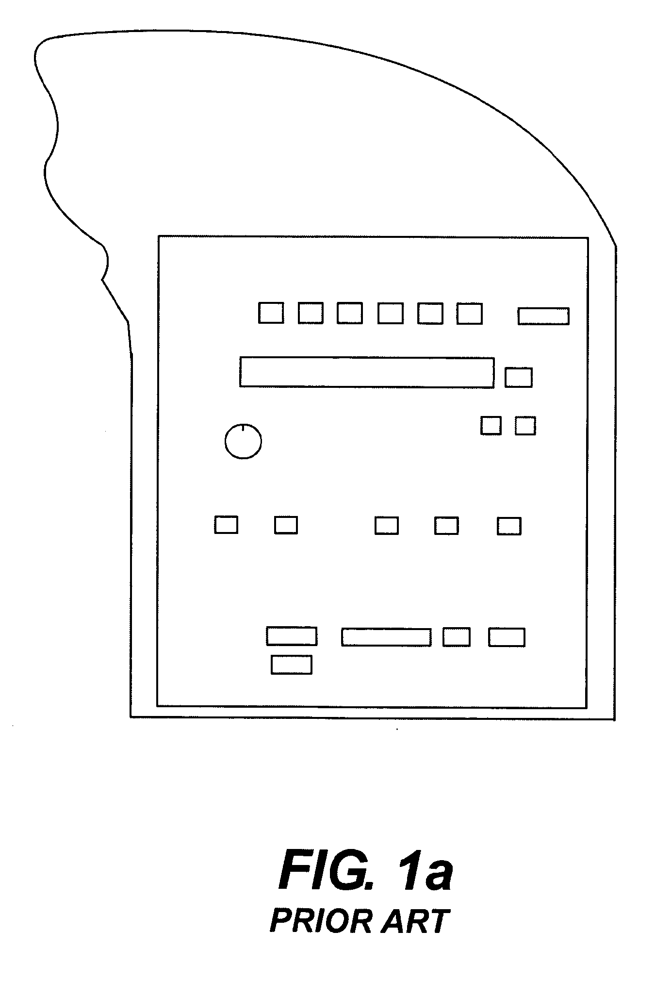
It is also noted, that the objectionable requirement to touch what one sees (and thus take ones eyes significantly off the road in many cases), has undoubtedly led manufacturers of the most recent set of navigational screens, to use a fixed set of keys as inputs, with the data display being the only thing programmable.
But the keys and switches used are by necessity small, and cluttered.
To conclude, conventional touch screens can work in vehicles, but in their form heretofore they have no tactile properties.

Method used


Image

  • Programmable tactile touch screen displays and man-machine interfaces for improved vehicle instrumentation and telematics
  • Programmable tactile touch screen displays and man-machine interfaces for improved vehicle instrumentation and telematics
  • Programmable tactile touch screen displays and man-machine interfaces for improved vehicle instrumentation and telematics

Examples


Embodiment Construction

FIG. 1

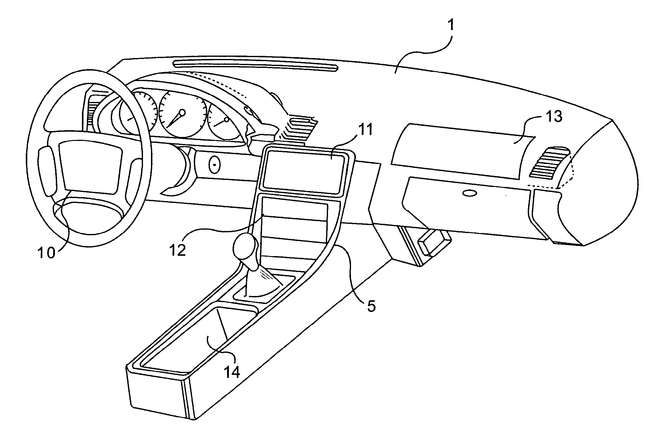
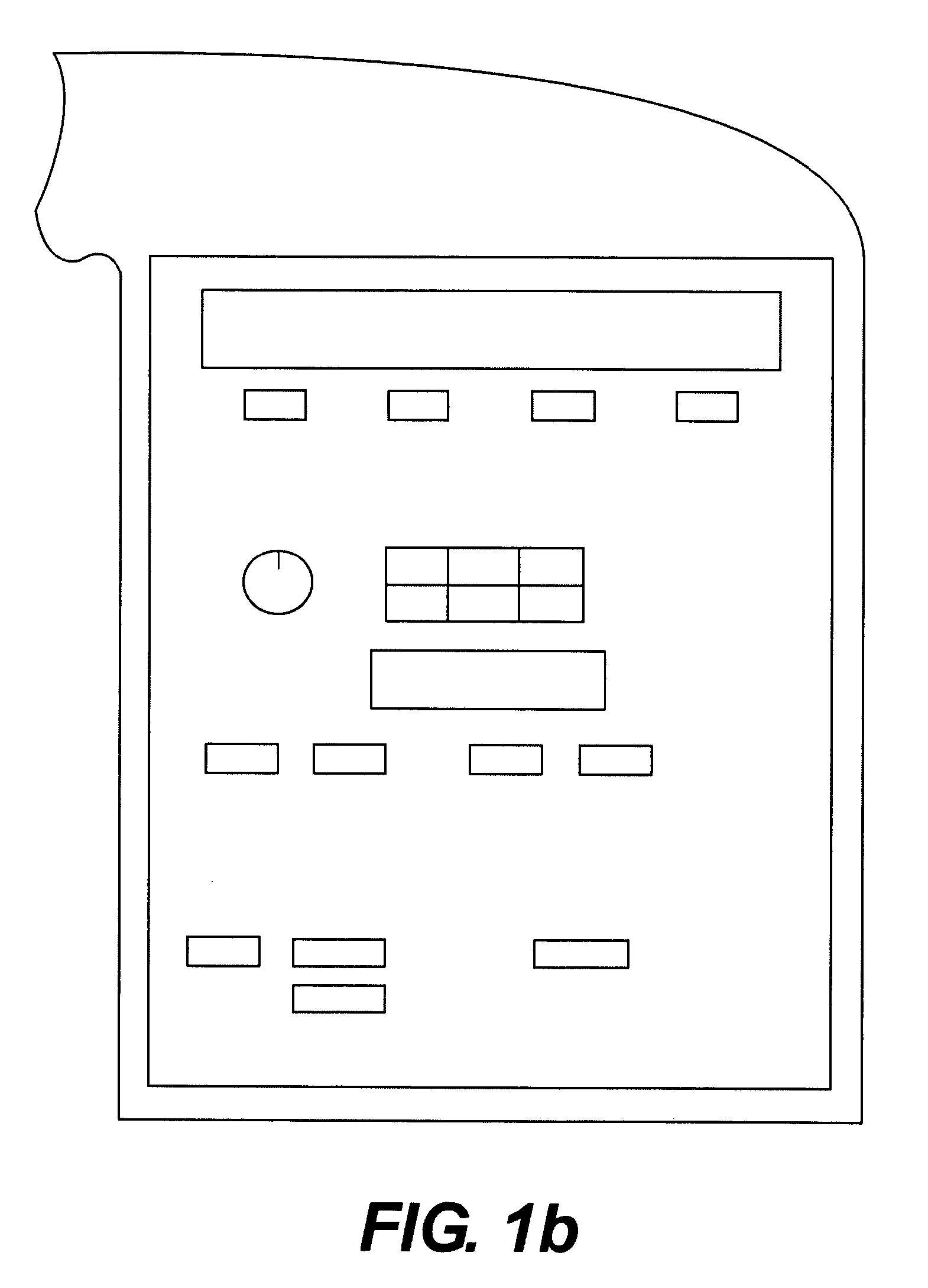
[0140]This invention is predominately aimed at providing a new form of instrument panel and related controls, based on displays, including touch screen displays, which have tactile attributes of considerable utility for the driver of the vehicle. By themselves, or in concert with voice techniques, these tactile displays enable the effective selection of functions in control related applications, not just in the vehicle, but in the home and elsewhere. Many of the disclosed embodiments are also thought to improve the safety of vehicle operation, while doing so at less manufacturing cost.

[0141]In a vehicle, tactile displays of the invention can be located on the passenger side (mainly for amusement and internet communication), on the driver's side as a replacement for the existing instrument cluster, or in the middle (also called center stack) which is the easiest to implement today because of lack of requirement of airbag application and the fact that the steering wheel does not...


PUM


Abstract

Disclosed are new methods and apparatus particularly suited for applications in a vehicle, to provide a wide range of information, and the safe input of data to a computer controlling the vehicle subsystems or “Telematic” communication using for example GM's “ONSTAR” or cellular based data sources. Preferred embodiments utilize new programmable forms of tactile touch screens and displays employing tactile physical selection or adjustment means which utilize direct optical data input. A revolutionary form of dashboard or instrument panel results which is stylistically attractive, lower in cost, customizable by the user, programmable in both the tactile and visual sense, and with the potential of enhancing interior safety and vehicle operation. Non-automotive applications of the invention are also disclosed, for example means for general computer input using touch screens and home automation systems.

Description

[0001]This application is a continuation of U.S. patent application Ser. No. 11 / 272,868, filed Nov. 15, 2005 (now U.S. Pat. No. ______), which is a continuation of U.S. patent application Ser. No. 09 / 789,538, filed Feb. 22, 2001 (now U.S. Pat. No. 7,084,859), which claims the benefit of U.S. Provisional Application No. 60 / 234,934 filed Sep. 26, 2000 and U.S. Provisional Application No. 60 / 183,807 filed Feb. 22, 2000. The disclosures of the above patent applications are hereby incorporated by reference in their entirety.BACKGROUND OF THE INVENTION[0002]This invention seeks to dramatically increase the utility of car informational displays and controls, while at the same time enhancing safety by improving sensory data presentation and ease of interaction with vehicle controls and data sources. The programmable nature of the disclosed devices also creates new methods for how data is delivered and utilized.[0003]The disclosed invention, including co-pending applications incorporated by ...

Claims


Application Information

Patent Timeline
Patent Type & Authority Applications(United States)
IPC IPC(8): G09G5/08G10L21/00G06F3/041
CPCB60K35/00B60K37/06B60K2350/1024B60K2350/1028B60K2350/901B60K2350/104G06F3/017G06F3/0416G06F3/04883B60K2350/1004B60K2350/102G06F3/016G06F3/04847B60K35/10B60K2360/11B60K2360/126B60K2360/143B60K2360/145B60K2360/1438B60K35/654
Inventor PRYOR, TIMOTHY R.
Owner APPLE INC
Learn More