Ir camera and method for use with ir camera

a technology of ir camera and focal plane array, which is applied in the field of ir camera, can solve the problems of reducing the image quality of ir camera, increasing the power consumption and manufacturing cost of the focal plane array, and different pixels showing slightly different temperature dependent behaviour. , to achieve the effect of simplifying the manufacturing process

Inactive Publication Date: 2009-11-05
FLIR SYST AB
View PDF2 Cites 95 Cited by
  • Summary
  • Abstract
  • Description
  • Claims
  • Application Information

AI Technical Summary

Benefits of technology

[0016]It is an object of the invention to provide a camera that will allow simpler manufacturing process.

Problems solved by technology

Also, slight pixel-to-pixel differences in the microbolometer structure, which arise in the manufacturing of these devices, may cause different pixels to exhibit slightly different temperature dependent behaviour.
This will cause image quality degradation of the IR camera if not corrected for.
One drawback with such a solution is that it increases the power consumption and manufacturing cost of the focal plane array significantly.
This recording of temperature calibration data at different temperatures is a cumbersome and time-consuming part of the manufacturing process of an IR camera.
However, for focal plane arrays operating without a thermo electric cooler, the pixel-to-pixel signal output change, caused by heating of cooling of the focal plane array, may be so large that image quality is negatively impacted in a time frame which is shorter than the desired non-uniformity correction frequency.
Non-uniformity correction is typically still performed during operation of the infrared camera to compensate for pixel-to-pixel variations not fully corrected for by the data collected during calibration.
This procedure, referred to as temperature cycling, is cumbersome, and requires a complex calibration environment.

Method used


Image

  • Ir camera and method for use with ir camera
  • Ir camera and method for use with ir camera
  • Ir camera and method for use with ir camera

Examples


Embodiment Construction

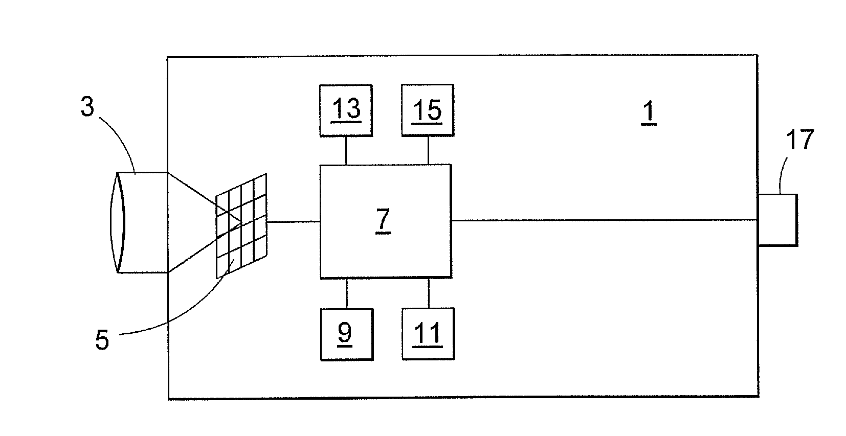
[0046]FIG. 1 illustrates an IR camera 1 in which the functions according to the invention may be implemented. The IR camera comprises IR optics 3 for focusing incoming radiation in the IR range onto a focal plan array 5 comprising a number of pixels, each arranged to produce an output signal in dependence of the incoming radiation.

[0047]The output signal from each pixel is fed to a processing unit 7 arranged to perform conventional processing on the signals. According to the invention, the processing unit 7 is also arranged to perform certain functions during calibration of the camera during manufacturing. The processing unit 7 is also arranged to perform certain compensation procedures during operation of the camera, to compensate for the temperature variations of the camera. According to an embodiment of the invention these compensation procedures differ from those common in the art, to take into account that the camera does not have calibration parameters for different ambient te...


PUM


Abstract

An infrared camera is arranged to compensate for temperature variations of the camera by
Recording the output signal of each pixel of the detector during a shutter operation Using the recorded signal from each pixel to update a temperature offset map stored in the camera to ensure uniform signal levels at different camera temperatures, Said code means being arranged to perform the following steps during operation of the camera:
    • save at least a first temperature offset map during a first shutter operation at a first temperature and a second temperature offset map during a second shutter operation at a second temperature
    • fit the data from the at least first and second offset maps to a curve
    • using the curve to compensate for variations in signal output caused by temperature variations.

Description

TECHNICAL FIELD [0001]The present invention relates to an IR camera and a method for use with an IR camera, to compensate for temperature changes of the camera during operation.BACKGROUND AND RELATED ART [0002]IR cameras are adapted to register incoming infrared radiation and present an image dependent on such radiation, typically displaying the temperature in various areas of the object. An IR camera typically comprises optics for focusing the radiation from an object onto a detector, such as a focal plane array. The focal plane array comprises a number of pixels, each pixel constituted, for example, by a microbolometer. The signal from a microbolometer type of focal plane array is related to the temperature of the microbolometer pixel structure. Each pixel is arranged to register incoming radiation in the infrared range, which causes an increase in temperature of the microbolometer. The temperature of the microbolometer is then converted into a signal output of the detector by mea...

Claims


Application Information

Patent Timeline
Patent Type & Authority Applications(United States)
IPC IPC(8): H04N5/33
CPCH04N5/33H04N17/002H04N5/3655H04N25/673
Inventor JONSSON, HENRIK
Owner FLIR SYST AB
Why Eureka
Try Eureka