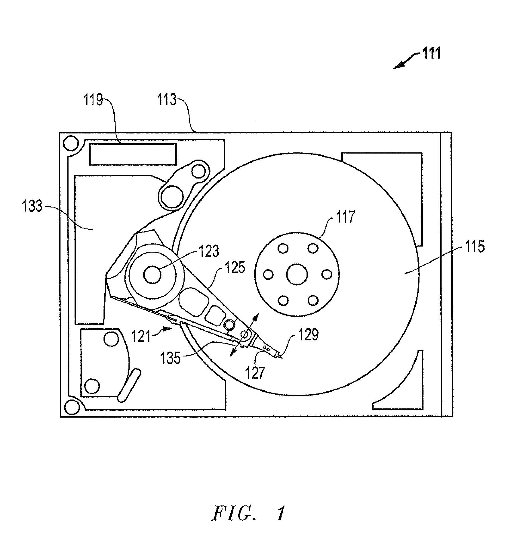
[0019]Referring to FIG. 1, a schematic drawing of one embodiment of an information storage system comprising a magnetic hard disk file or drive 111 for a computer system is shown. Drive 111 has an outer housing or base 113 containing at least one magnetic disk 115. Disk 115 is rotated by a spindle motor assembly having a central drive hub 117. An actuator 121 comprises one or more parallel actuator arms 125 in the form of a comb that is pivotally mounted to base 113 about a pivot assembly123. A controller 119 is also mounted to base 113 for selectively moving the comb of arms 125 relative to disk 115.
[0020]In the embodiment shown, each arm 125 has extending from it at least one cantilevered load beam and suspension 127. A magnetic read/write transducer or head is mounted on a slider 129 and secured to a flexure that is flexibly mounted to each suspension 127. The read/write heads magnetically read data from and/or magnetically write data to disk 115. The level of integration called the head gimbal assembly is the head and the slider 129, which are mounted on suspension 127. The slider 129 is usually bonded to the end of suspension 127. The head is typically formed from ceramic or intermetallic materials and is pre-loaded against the surface of disk 115 by suspension 127.
[0021]Suspensions 127 have a spring-like quality which biases or urges the air bearing surface of the slider 129 against the disk 115 to enable the creation of the air bearing film between the slider 129 and disk surface. A voice coil 133 housed within a voice coil motor magnet assembly 134 is also mounted to arms 125 opposite the head gimbal assemblies. Movement of the actuator 121 (indicated by arrow 135) by controller 119 moves the head gimbal assemblies radially across tracks on the disk 115 until the heads settle on their respective target tracks.
[0022]Referring now to FIGS. 2-5, representative embodiments of a system, method, and apparatus for preventing the accumulation of excess lubrication in the form of lubricant lines on magnetic media for disk drives are shown. As depicted in FIG. 2, the system comprises a reservoir or bath 201 containing a volume of solution or lubricant 203 as is known by those having ordinary skill in the art. For example, the lubricant 203 may comprise a low concentration of lubricant and a volatile solvent that evaporates after the lubricant is applied.
[0023]One or more media disks 115 (e.g., one shown for simplicity) are located on a fixture 205 adjacent the bath 201. The fixture 205 is used to support and dip the media disk 115 in the volume of lubricant 203 in the bath 201. The fixture 205 has a mandrel 207 with an axis 209. A plurality of partitions or dividers 211 are mounted to the mandrel 207. The dividers 211 axially abut one another (e.g., in a parallel configuration) to define slots 213 therebetween. Alternatively, the dividers 211 may be formed as a single component that mounts to the mandrel 207. Each slot 213 is designed to support one of the media disks 115. Each slot 213 may comprise a circular groove formed between adjacent ones of the dividers 211.
[0024]In operation, the disks 115 are retained on the mandrel 207 by the slots 213 between the dividers 211. The disks 115 are lowered and submerged in the lubricant 203 and then removed therefrom at a constant rate. The lubricant is uniformly distributed over the surfaces of the disks 115. During the lube dipping process, the disks are fully immersed beneath the surface of the lubricant solution in a deep bath. The disks are then removed from the bath at a selected rate of speed that controls the thickness of the lubricant that remains on the disks.
[0025]It is the unique designs and shapes of the dividers 211 that prevent the lubricant 203 from forming waves in the bath 201. In one embodiment (FIG. 5), each divider 211 has an axial cross-sectional shape that resembles an inverted tear drop.
[0026]Each divider 211 may be provided with an upper end 215, two side edges 217, and a lower end 219, each of which is axially spaced apart from the upper ends 215, side edges 217 and lower ends 219 of other ones of the dividers 211 as best shown in FIGS. 3 and 4. The upper ends 215 and side edges 217 are generally arcuate or circular in shape, while the lower ends 219 are pointed in shape. The upper ends 215 protrude above the mandrel 207 by an upper distance. The side edges 217 protrude laterally from the mandrel 207 by a side distance that is greater than or equal to the upper distance. The lower ends 219 protrude below the mandrel 207 by a lower distance that is greater than the side distance. Bach divider 211 comprises a rounded partition that is curved both axially and radially with respect to the axis 209. Each rounded partition has a lower end 219 that tapers both axially and radially to a point as shown. The same configuration may be used when the dividers are formed as a single component.
[0027]In still other embodiments, the shape of the dividers is not limited to inverted tear drop designs. Alternate shapes may be used such as pointed or spiked shapes that significantly diminish or eliminate the agitation of the liquid surface of the lubricant solution when removing the disks from the bath.
[0028]The invention also comprises an apparatus for forming a lubricant layer on media disks, as described herein, that may be used to function as a component of the overall system. The invention further comprises a method of lubricating media disks. For example, in one embodiment, the method comprises providing a fixture with a mandrel having an axis and dividers mounted to the mandrel, the dividers axially abutting one another to define slots between the dividers; supporting media disks on the fixture such that each slot supports one of the media disks; placing a volume of lubricant in a bath; lowering the media disks with the fixture to dip the media disks in the volume of lubricant; and lifting the media disks out of the volume of lubricant with the fixture such that the dividers reduce a level of agitation of the a surface of the volume of lubricant.
[0029]The method also may comprise providing each divider with an axial cross-sectional shape that resembles an inverted tear drop; or providing each divider with an upper end, two side edges, and a lower end, each of which is axially spaced apart from the upper ends, side edges and lower ends of other ones of the dividers. As shown and described herein, the upper ends and side edges are generally arcuate, and the lower ends are pointed. Alternatively, the upper ends protrude above the mandrel by an upper distance, the side edges protrude laterally from the mandrel by a side distance that is greater than or equal to the upper distance, and the lower ends protrude below the mandrel by a lower distance that is greater than the side distance. The method also may comprise providing each slot as a circular groove formed between adjacent ones of the dividers; or providing each divider as a rounded partition that is curved both axially and radially with respect to the axis, and each rounded partition has a lower end that tapers both axially and radially to a point.
[0030]To test the invention, a transparent lubricant draining bath was constructed, and a video microscope was set up for direct observation of the lubricant “dipping” process. Microscopic video footage of the process clearly demonstrated that excess lubricant lines are caused by the surface waves of the liquid lubricant level as it drops suddenly from the bottom edge of the disk holder. Video microscopic observation of the process clearly indicates that a fixture constructed in accordance with the invention diminishes the surface waves in the lubricant bath. Optical surface analyzer imaging of disks demonstrates that the invention effectively prevents the formation of lubricant lines on disks.
[0031]While the invention has been shown or described in only some of its forms, it should be apparent to those skilled in the art that it is not so limited, but is susceptible to various changes without departing from the scope of the invention.