Method for estimation of indicated mean effective pressure for individual cylinders from crankshaft acceleration

a technology of internal combustion engine and effective pressure, which is applied in the direction of electrical control, process and machine control, etc., can solve the problems of inability to carry, large amount of analysis equipment on the rack, and inability to accurately estimate the effective pressure of individual cylinders, so as to reduce the level of calibration effort, eliminate the expense and intrusion of direct imep measurement, and reduce the effect of calibration parameters

Active Publication Date: 2009-11-05
DELPHI TECH IP LTD
View PDF12 Cites 36 Cited by
  • Summary
  • Abstract
  • Description
  • Claims
  • Application Information

AI Technical Summary

Benefits of technology

[0026]1. accurate, by-cylinder / engine IMEP, and by-cylinder / engine COVIMEP calculations using only tooth error-corrected engine speed and quasi-steady engine indicated torque algorithm to both “seed” and re-center the total cylinder torque estimate, and a commercially available engine control unit which eliminates the expense and intrusiveness of direct IMEP measurements with pressure sensors;
[0027]2. state space analytical technique which significantly reduces the level of calibration effort needed to parameterize the model. The current invention utilizes readily-available steady state engine dynamometer (“mapping”) data for the determination of the quasi-steady component of cylinder torque. For the most part, the calibration parameters are reduced to physical constants of the engine and readily available steady state engine dynamometer (“mapping”) data. Calibration effort expended to refine torque estimates can benefit other users of the torque data. Since this quasi-steady indicated torque estimate is generally available and in use in prior art engine controls, the present method requires no additional calibration or engine parameterization for this part of the solution;
[0029]4. use of the Coefficient of Variance (COVIMEP) metric, and COVIMEP calculations which are optimized to minimize chronometric impacts and have good utility for real time engine control; and

Problems solved by technology

Although IMEP is a valuable parameter for combustion development, its use in real time engine controls has been limited in the prior art in general because its determination has required expensive and non-durable combustion analysis equipment, and because the prior art methods of measurement have been engine-intrusive (e.g., combustion pressure sensors in the engine heads or spark plugs).
Other known methods of combustion quality measurement, such as Ion Sense technology, require expensive hardware upgrades and have not been generally available.
Off-board rack-type analysis equipment is bulky, expensive, and non-portable.
Thus, engine control using IMEP has been largely a laboratory phenomenon rather than being useful day-to-day in an operating vehicle.
Less than ideal combustion performance can arise from a variety of sources including: engine component design limitations; variations in fuel properties in the field; aged engine components; and manufacturing tolerances of engine subassemblies and components.
When attempting to evaluate combustion quality, quantifying only single-cylinder events can be misleading due to cyclic variability of fuel transients in the ports, or to unburned fuel residuals which remain after partial burns or misfires.
Incomplete mixing and burn due to in-cylinder turbulence which is unrepresentative of overall combustion behavior may also result in poor combustion on a single cylinder event basis.
In addition to the lack of a good metric for evaluating combustion quality that can be used in real time control, prior art methods have also required additional development effort to calibrate their models.
While such development effort is of value for improving the model's accuracy, it provides limited additional benefit beyond the express purpose of individual cylinder torque estimation.
Further, depending on complexity, prior art methods can be computationally expensive which limits their use, especially at high engine speeds when the chronometric impact of calculations which must be performed in the period between cylinder firing events, i.e. calculations for individual cylinder torque estimation, is greatest.

Method used


Image

  • Method for estimation of indicated mean effective pressure for individual cylinders from crankshaft acceleration
  • Method for estimation of indicated mean effective pressure for individual cylinders from crankshaft acceleration
  • Method for estimation of indicated mean effective pressure for individual cylinders from crankshaft acceleration

Examples


Embodiment Construction

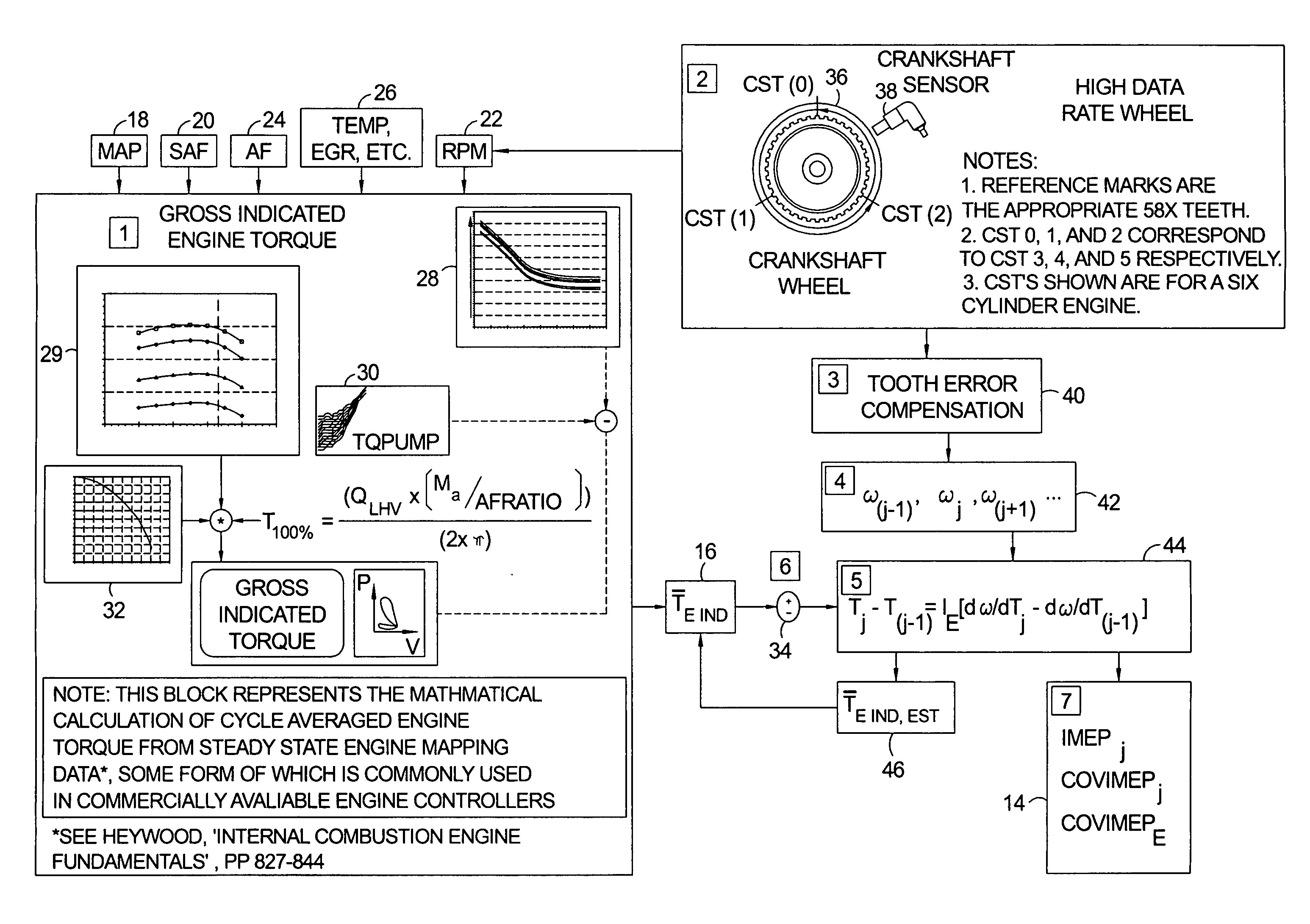
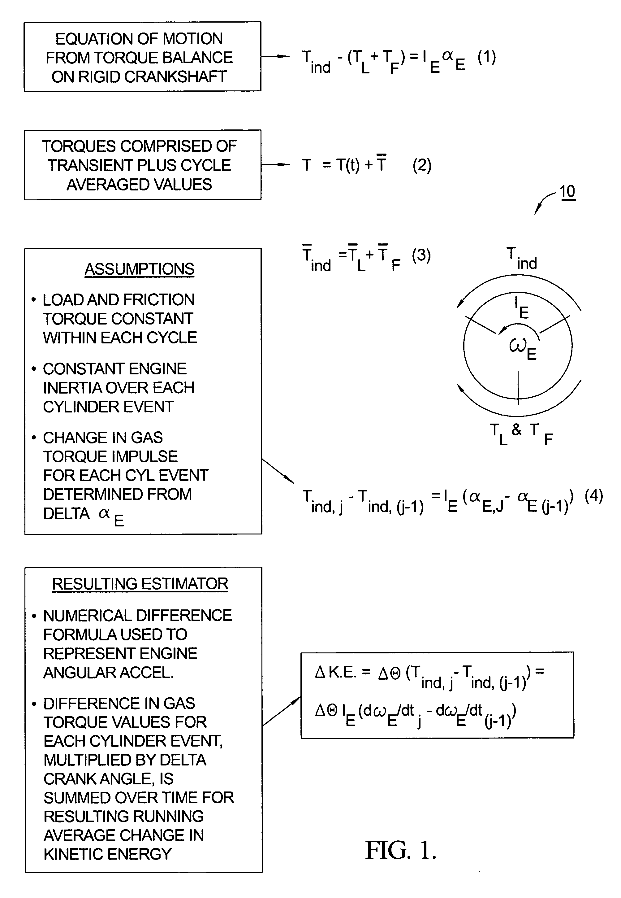
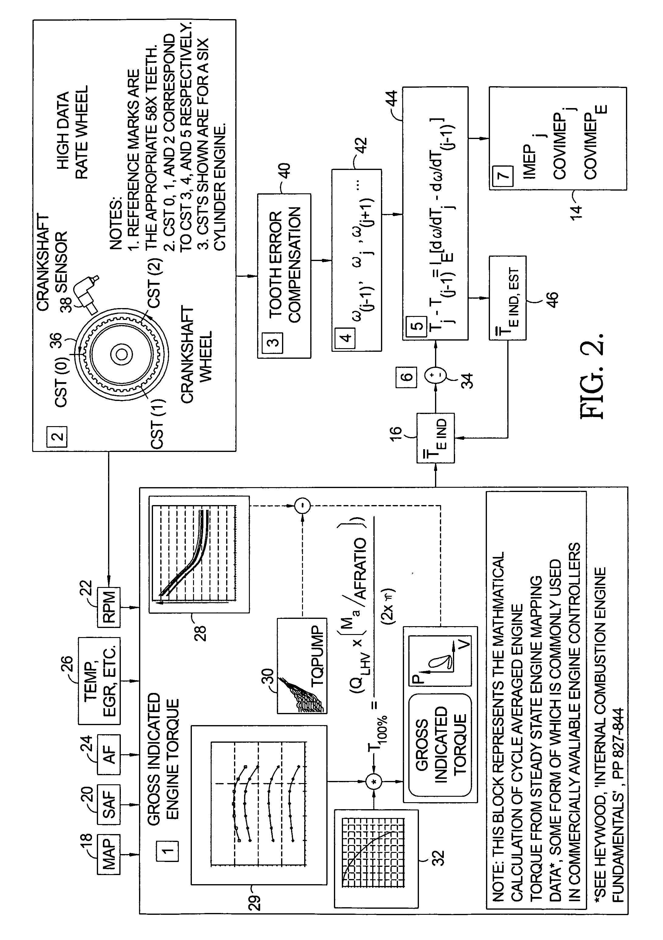
[0037]The transient inter-cycle indicated torque component may be determined in two ways: either indirectly, through calculation of engine kinetic energy change via the difference in average torque from one cylinder event to the next multiplied by the crank angle over which average torque difference acts, or directly, through changes in measured instantaneous crank shaft velocities from one cylinder event to the next. For illustration purposes, the development of average torque changes (indirect method) will be described in detail here.

[0038]Referring to FIG. 1, a torque balance on a rigid crankshaft of an internal combustion engine is illustrated in Diagram 10. Gas or indicated torque (Tind) is assumed to act through the piston and connecting rod assembly at the crank / connecting rod interface. As a first approximation, an average cylinder torque is assumed to act over a crank angle range (ωE), the location of which is optimized for capturing the total energy contribution of the cur...


PUM


Abstract

A method for inferring Indicated Mean Effective Pressure as total transient indicated engine torque in an internal combustion engine, comprising the steps of acquiring at least one crankshaft time stamp for use in determining a cylinder-specific engine velocity; calculating an incremental change in engine kinetic energy from the previously fired cylinder (j−1st) to the currently fired (jth) cylinder using the cylinder-specific engine velocity; equating the incremental change in engine kinetic energy to a change in energy-averaged cylinder torque (IMEP) from the previously-fired (j−1st) to a currently-fired (jth) cylinder; summing a plurality of the incremental changes in engine kinetic energy over time to determine a value of the transient component of indicated torque; determining a value of the quasi-steady indicated engine torque; and adding the value of transient component of indicated torque to the value of quasi-steady indicated engine torque to yield the Indicated Mean Effective Pressure.

Description

TECHNICAL FIELD[0001]The present invention relates to a method of estimating individual average cylinder torque values of internal combustion engines; more particularly, to methods for optimizing operating parameters such as combustion mixtures and spark timing in such engines; and most particularly, to an improved method for inferentially determining Indicated Mean Effective Pressure (IMEP) for individual cylinders by calculation from instantaneous changes in crankshaft acceleration, and to a method for engine control employing improved IMEP calculation.BACKGROUND OF THE INVENTION[0002]Knowledge of individual cylinder values of Indicated Mean Effective Pressure (IMEP) is known in the prior art as a powerful tool for evaluating and correcting poor combustion in an internal combustion engine. By definition, IMEP, in kiloPascals, is defined as the ratio of the indicated work in Newton meters (W) divided by the swept volume per cylinder (V) in liters:IMEP=W / V  (Equation 0)[0003]IMEP is...

Claims


Application Information

Patent Timeline
Patent Type & Authority Applications(United States)
IPC IPC(8): F02D45/00
CPCF02D41/0097F02D41/1497F02D2200/1004F02D2200/1012
Inventor RACKMIL, CHARLES I.MCKAY, DANIEL L.MALACZYNSKI, GERARD W.
Owner DELPHI TECH IP LTD
Why Eureka
Try Eureka