Enhanced nitrogen removal in an LNG facility

a nitrogen removal and nitrogen technology, applied in the field of liquefying natural gas, can solve the problems of difficult condensation of gas, difficult operation, and high cost of pressure-containing vessels for storage and transportation

Active Publication Date: 2009-11-12
CONOCOPHILLIPS CO
View PDF13 Cites 55 Cited by
  • Summary
  • Abstract
  • Description
  • Claims
  • Application Information

AI Technical Summary

Problems solved by technology

Some methods produce a pressurized LNG (PLNG) product that is useful, but requires expensive pressure-containing vessels for storage and transportation.
High nitrogen concentrations in the natural gas feed stream can present several operational problems as the gas is subjected to liquefaction in an LNG facility.
For example, the natural gas can be difficult to condense, thereby increasing the compressor horsepower requirements.
Liquefying natural gas having an increased nitrogen concentration can also lead to larger volumes of off-spec LNG and lower quality fuel gas for use within the facility.
Problems with high-nitrogen natural gas can be further exacerbated when the LNG facility employs one or more open-loop refrigeration cycles that utilize at least a portion of the natural gas feed stream as a refrigerant.
Although highly desirable and even necessary in some cases, conventional processes of removing nitrogen from the natural gas liquefied in an LNG facility can be expensive.
Typical nitrogen removal units (NRUs) process large volumes of methane-containing intermediate process streams having relatively dilute, but nonetheless undesirable, concentrations of nitrogen.
Processing these larger volumes of more nitrogen-dilute process streams increases the overall cost of nitrogen removal, in terms of capital, maintenance, and operating costs.

Method used


Image

  • Enhanced nitrogen removal in an LNG facility
  • Enhanced nitrogen removal in an LNG facility
  • Enhanced nitrogen removal in an LNG facility

Examples


Embodiment Construction

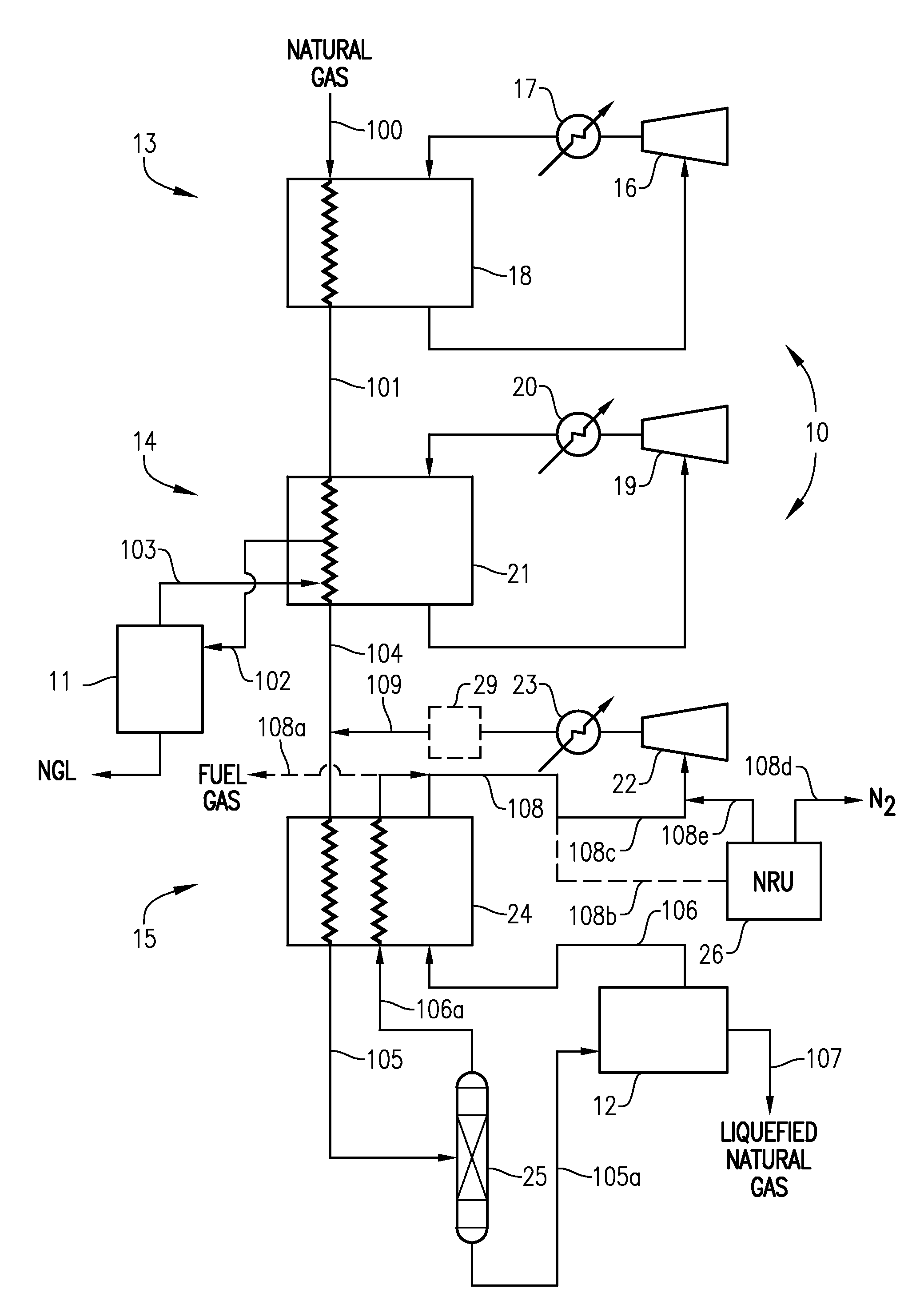
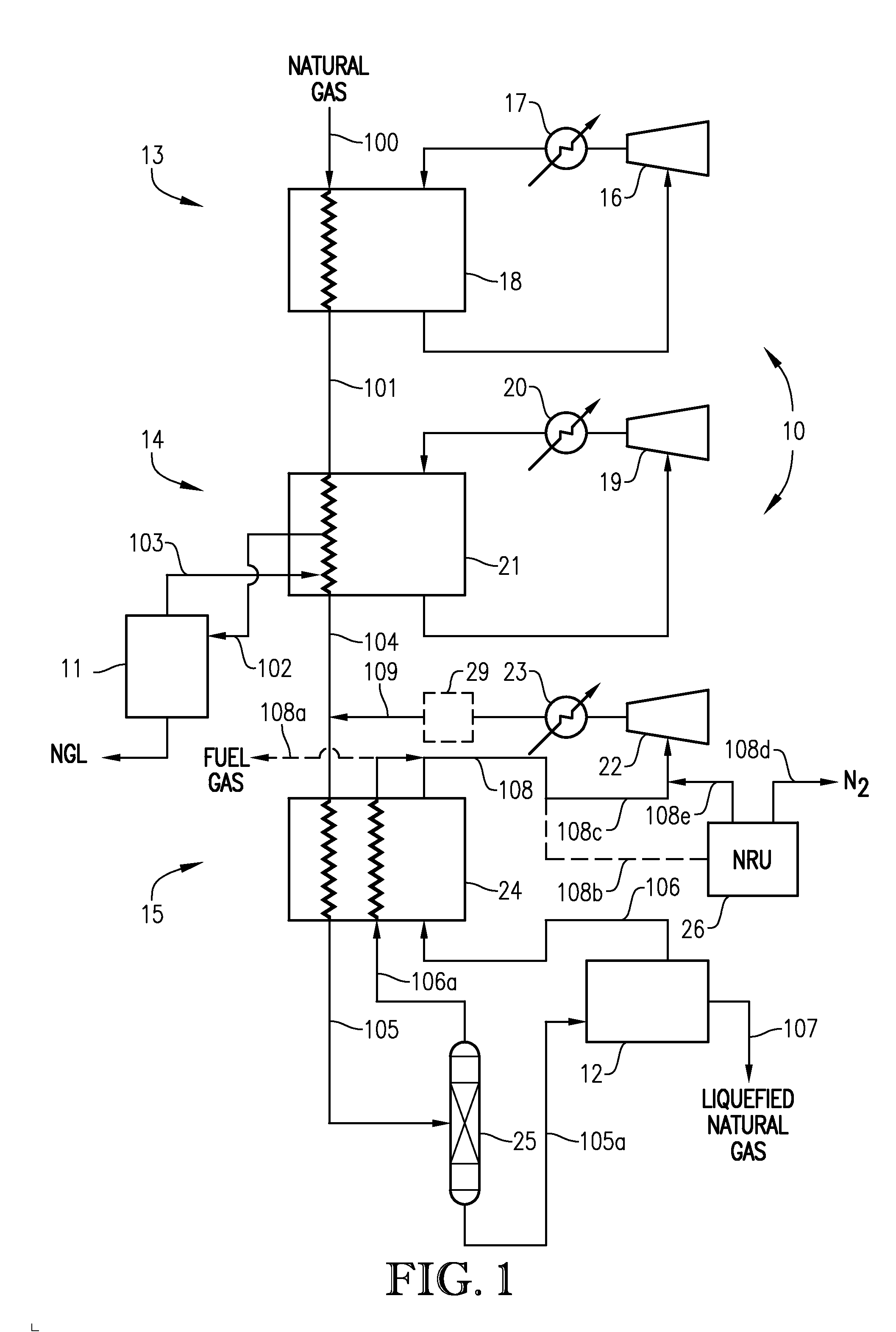
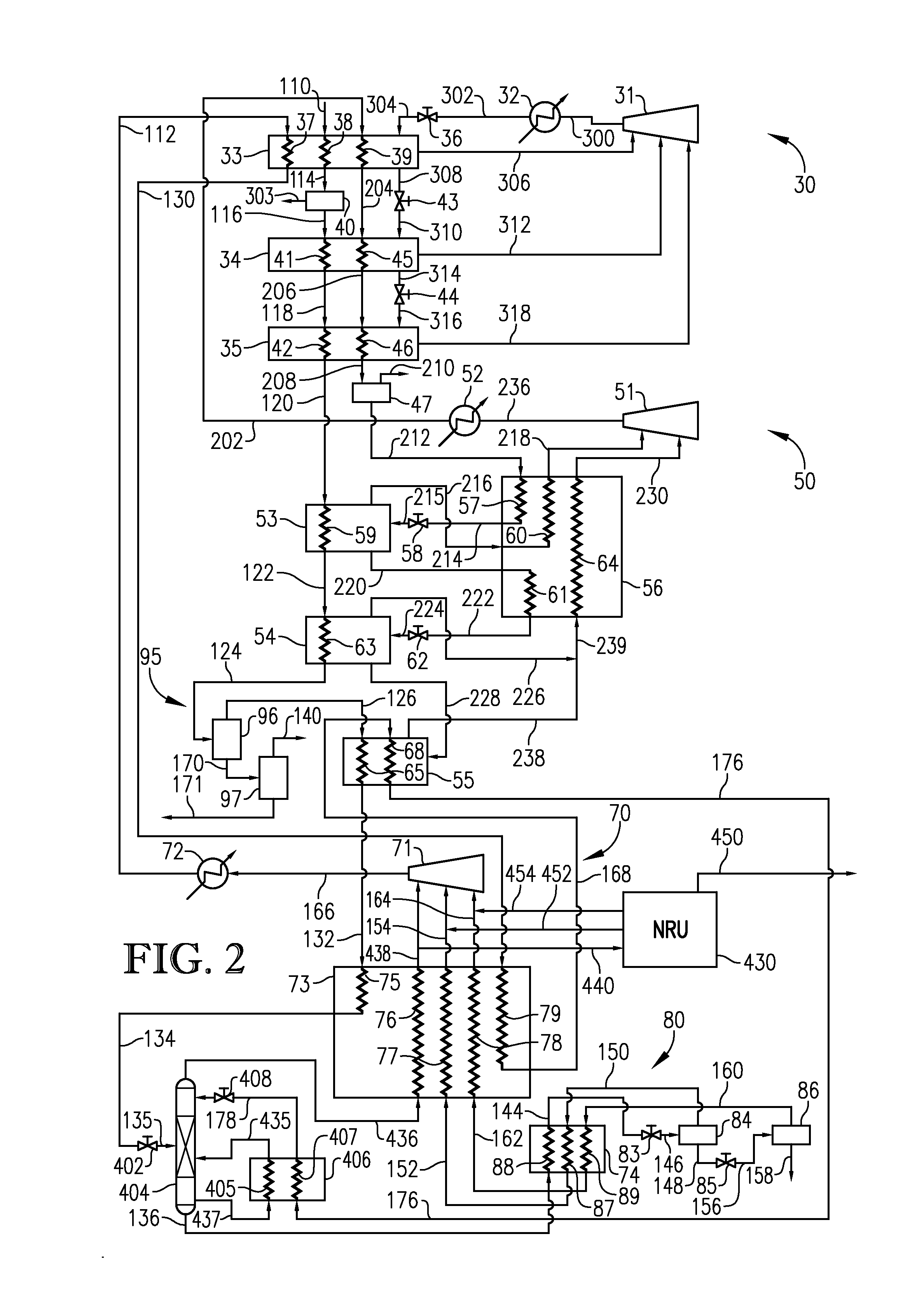
[0018]The present invention can be implemented in a facility used to cool natural gas to its liquefaction temperature to thereby produce liquefied natural gas (LNG). In general, the LNG facility comprises a plurality of refrigeration cycles that employ one or more refrigerants to extract heat from the natural gas and then reject the heat to the environment. In one embodiment, the LNG facility in which the present invention is incorporated into or used in combination with can comprise at least one, at least two, or at least three or more refrigeration cycles. Numerous configurations of LNG systems exist, and the present invention may be implemented in many different types of LNG systems.

[0019]In one embodiment, the present invention can be implemented in a mixed refrigerant LNG system. Examples of mixed refrigerant processes can include, but are not limited to, a single-loop refrigeration system using a mixed refrigerant, a propane pre-cooled mixed refrigerant system, and a dual mixe...


PUM


Abstract

An LNG facility employing an enhanced nitrogen removal system that concentrates the amount of nitrogen in the feed stream to a nitrogen removal unit (NRU) to thereby increase the separation efficiency of the NRU. In one embodiment, the nitrogen removal system comprises a multistage separation vessel operable to separate nitrogen from a cooled natural gas stream. At least a portion of the resulting nitrogen-containing stream exiting the multistage separation vessel can be used as a refrigerant, processed to a nitrogen removal unit, and / or utilized as fuel gas for the LNG facility.

Description

BACKGROUND OF THE INVENTION[0001]1. Field of the Invention[0002]This invention relates to methods and apparatuses for liquefying natural gas. In another aspect, the invention concerns an LNG facility employing an enhanced nitrogen removal system.[0003]2. Description of the Related Art[0004]Cryogenic liquefaction is commonly used to convert natural gas into a more convenient form for transportation and / or storage. Because liquefying natural gas greatly reduces its specific volume, large quantities of natural gas can be economically transported and / or stored in liquefied form.[0005]Transporting natural gas in its liquefied form can effectively link a natural gas source with a distant market when the source and market are not connected by a pipeline. This situation commonly arises when the source of natural gas and the market for the natural gas are separated by large bodies of water. In such cases, liquefied natural gas (LNG) can be transported from the source to the market using spec...

Claims


Application Information

Patent Timeline
Patent Type & Authority Applications(United States)
IPC IPC(8): F25J3/00
CPCF25J1/0022F25J2270/88F25J1/0052F25J1/021F25J1/023F25J1/0238F25J1/0241F25J1/0283F25J3/0209F25J3/0233F25J3/0257F25J2200/02F25J2200/70F25J2220/62F25J2220/64F25J2270/12F25J1/0265F25J2215/04F25J2200/40F25J2200/78F25J1/004F25J2200/76F25J2200/08F25J2200/10
Inventor RANSBARGER, WELDON L.ORTEGO, JR., J. DALE
Owner CONOCOPHILLIPS CO
Why Eureka
Try Eureka