[0022]In broad terms, the invention provides a fuel injector and a method for operating a fuel injector that achieve benefits of direct-acting and hydraulic servo fuel injector designs, while reducing disadvantages associated with such known systems. In part, the invention provides a fuel injector that provides the advantages of a direct-acting fuel injector, but at a lower cost and without the limitations on fuel pressure and fuel flow rate. The invention further relates to a fuel injector and a method for operating a fuel injector in which the parasitic servo flow of fuel associated with prior art servo mechanisms is injected into an engine cylinder, rather than being returned to the
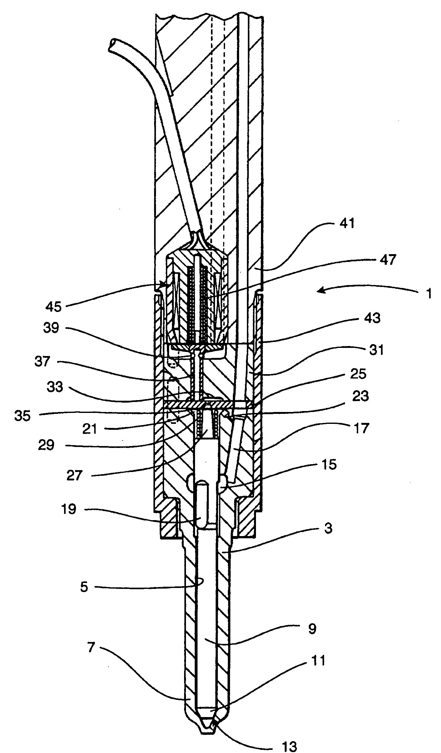
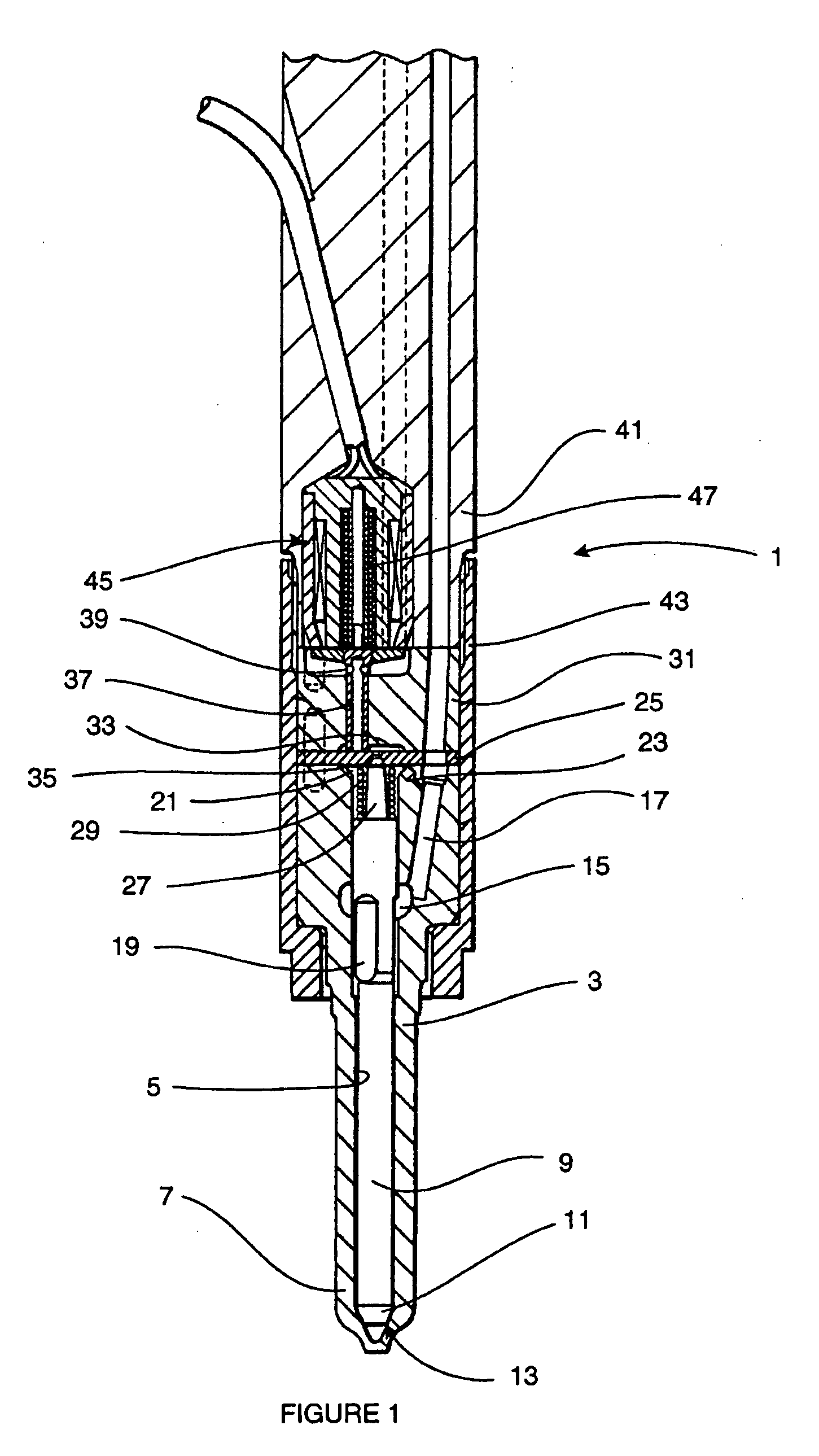
fuel supply. In part the invention relates to a fuel injector having two valve needles, the position of one of the valve needles being controlled directly by way of an actuating mechanism, and the position of the other being controlled indirectly by way of a servo flow. In this way, one or more advantages over the prior art may be achieved, for example: the servo flow is no-longer parasitic as it is injected; servo flows can be relatively large as they are doing useful work, so response speed can be high; no back-leak connection to the
fuel supply is required on the injector and no heat is returned to the fuel supply; small injections are controlled directly and so are not subject to servo lags; needle lift for large injections is not limited by actuator capabilities.
[0032]In particularly suitable embodiments, the first valve member is provided with a first valve bore, and the second valve member is received within the first valve bore. The first valve bore provides a path of fluid communication (for fuel) between the injection control chamber and a set of nozzle outlets associated with the second valve member. Advantageously, the first valve bore extends along the central axis of the first valve member. The second valve member is suitably a clearance fit within the bore, in use to permit fuel from the injection control chamber to pass between the (inner) surface of the first valve bore and the (outer surface of the) second valve member towards the tip of the second valve member. Thus, engagement of the second valve member with its associated (second) seating region prevents the injection of fuel from the injection control chamber (via the fluid communication path between the bore of the first valve member and the second valve member).
[0033]The fuel injector of the invention may comprise a second
valve seat member which has a surface defining the second seating region associated with the second valve member. In a beneficial embodiment the second
valve seat member is arranged to substantially prevent fluid communication between the first set of nozzle outlets and the second set of nozzle outlets, where the first and second valve members control the injection of fuel from separate sets of nozzle outlets. In another embodiment, however, the second
valve seat may be adapted to enable fluid communication between the first valve bore and the set of nozzle outlets associated with the first valve member when the second valve member is disengaged from the second seating region. In this way, the first and second valve members may control the injection of fuel through the same set of nozzle outlets. Advantageously, the second valve seat is arranged as a guide for the first valve member. Thus, at least a part of the second valve seat is a close fit with the first valve bore in the region of the tip of the first valve member.
[0039]In another embodiment, the actuator comprises a piezoelectric actuator. Advantageously, in this embodiment there may be provided a hydraulic
coupling between the piezoelectric actuator and the second valve member. In this way the responsiveness (i.e. the extent of translational movement) of the second valve member can be controlled relative to the
length change of the piezoelectric actuator, as described in EP 0995901, by way of example. Typically, the hydraulic
coupling is adapted to compensate for any slow length changes that may occur in the piezoelectric actuator as a result of variations in factors such as pressure and temperature. In this way, the second valve member is not inadvertently disengaged from its seating region as a result of changes in engine and / or environmental parameters or piezoelectric properties of the actuator. Conveniently, the hydraulic
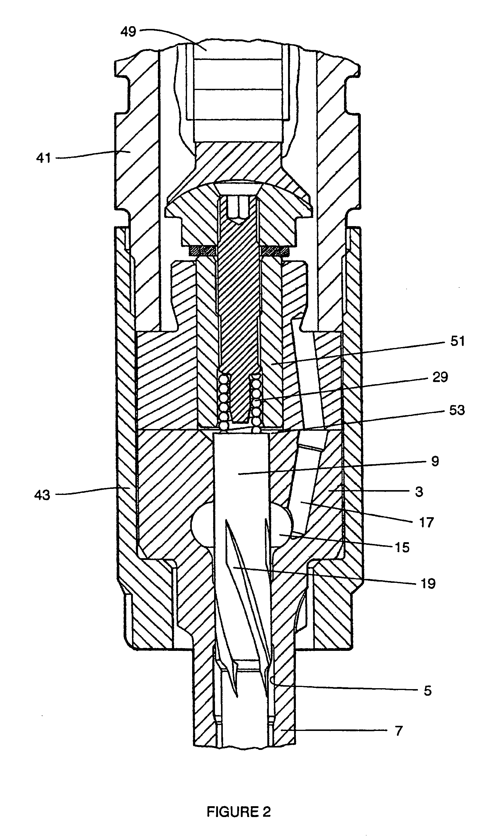
coupling may also (or alternatively) serve to amplify the movement of the piezoelectric actuator so that the second valve member moves a greater distance that the
length change of the actuator. Amplification of the movement of the piezoelectric actuator may suitably be achieved by way of a
piston member of larger
diameter than the second valve member (as shown in FIG. 2).

