
Link training scheme for displayport source repeaters

Active Publication Date: 2009-11-12
PARADE TECH
View PDF10 Cites 43 Cited by
  • Summary
  • Abstract
  • Description
  • Claims
  • Application Information

AI Technical Summary

Benefits of technology

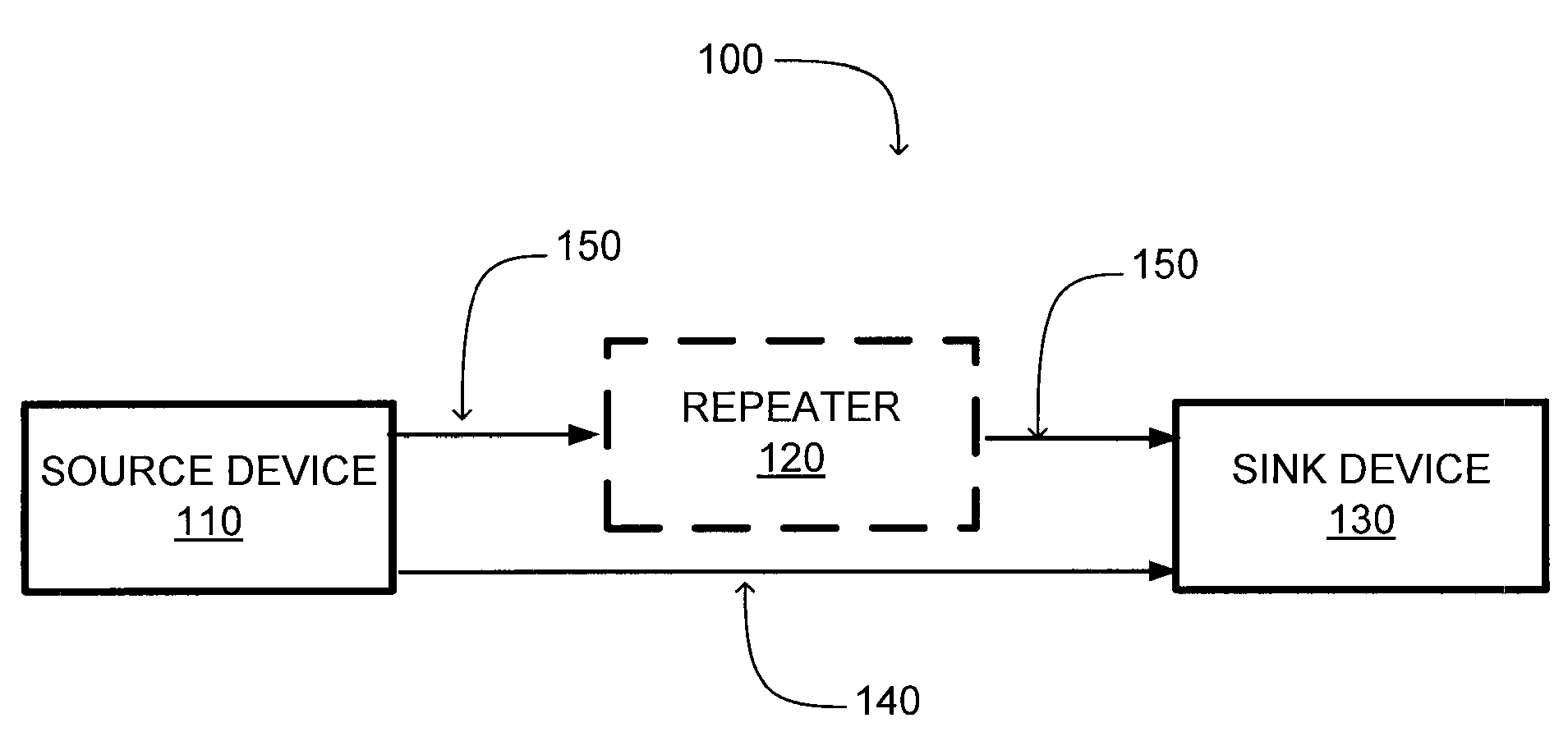
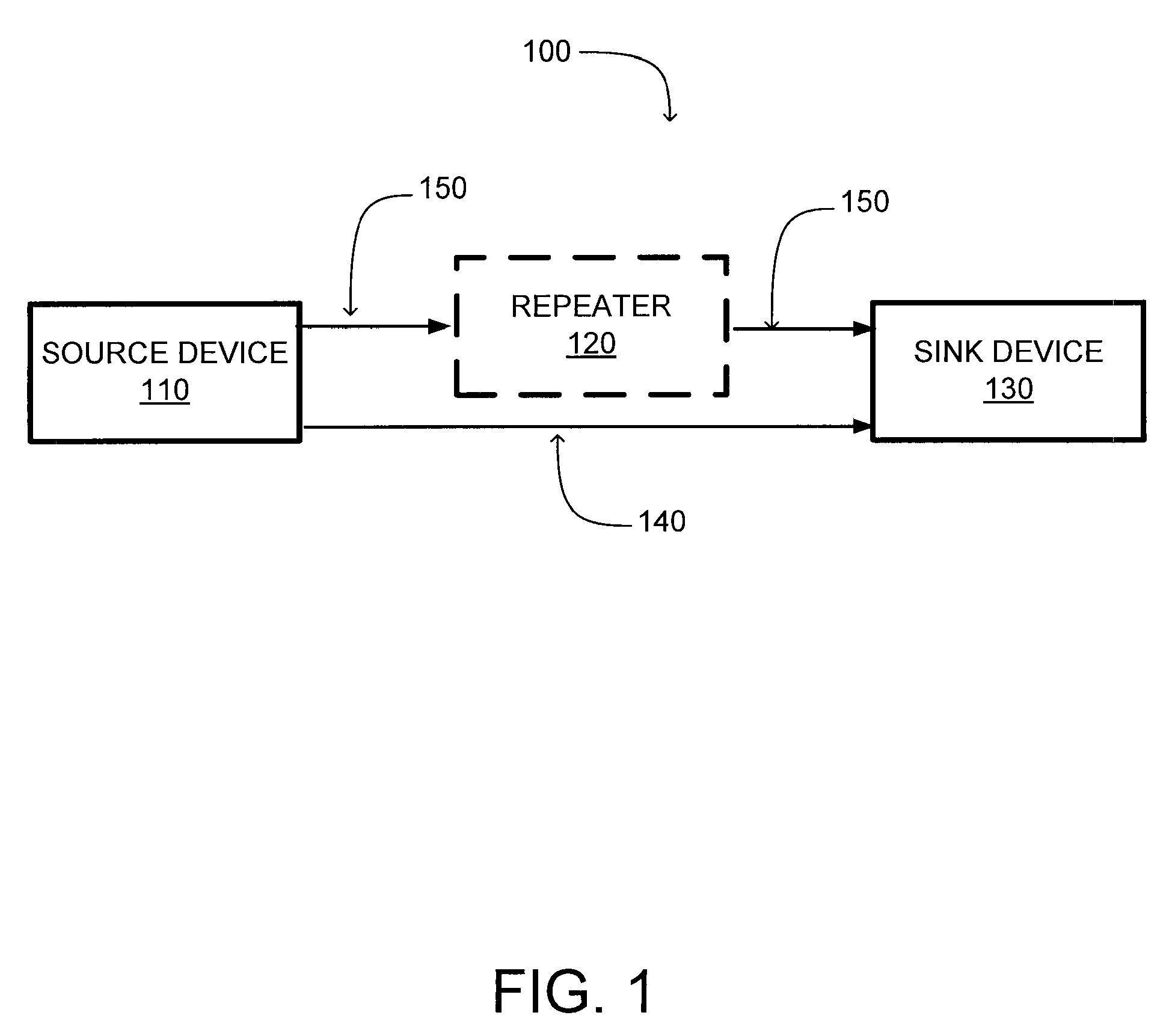
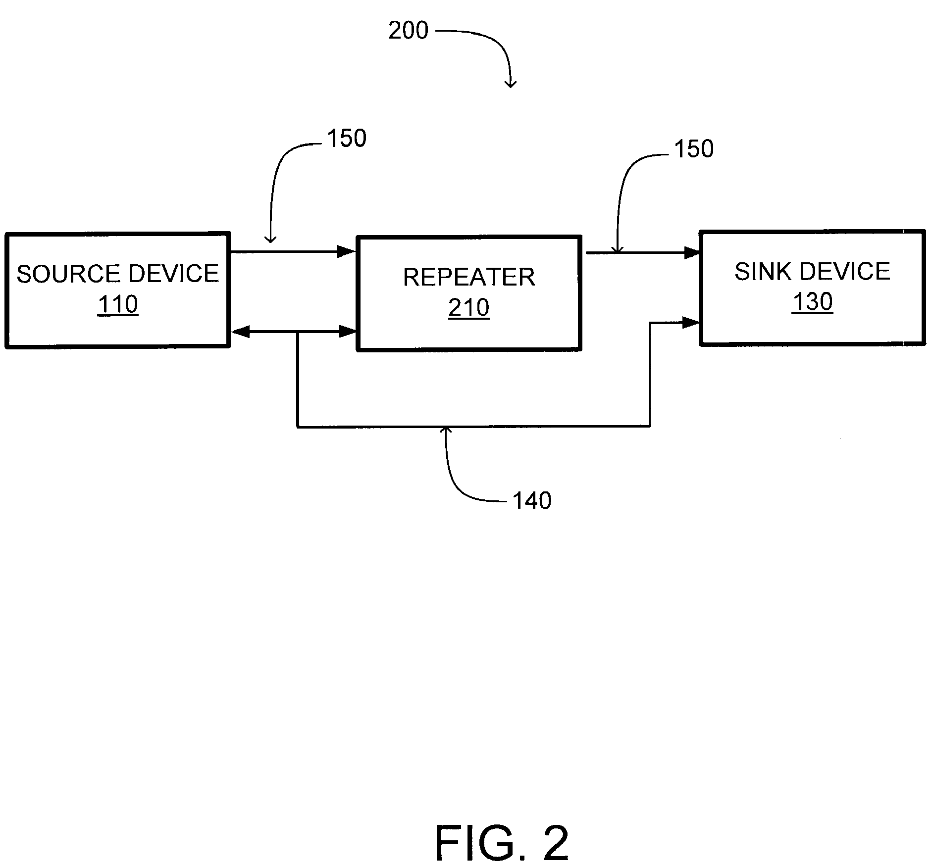
[0007]In an embodiment, a repeater comprises a listening module which is coupled to an auxiliary communication channel which communicates configuration data between a source device and a sink device. The listening module captures configuration data that is transmitted using the auxiliary communication channel. An interceptor is coupled to the listening module and classifies configuration data captured by the listening module. The interceptor allows generation of a subset of the captured configuration data having specific characteristics, such as data associated with link training. A parameter setting module is coupled to the interceptor and modifies a configuration setting of the repeater responsive to a subset of the captured configuration data. This allows the repeater to be configured responsive to data transmitted between the source device and the sink device so that the repeater and source device are configured using the same configuration data. This beneficially allows the repeater to more accurately replicates the characteristics of the source device.
[0008]In an embodiment, a communication channel is established between a source device and a repeater and used to communicate data. An auxiliary communication channel is also established between the source device and the sink device and used to communicate configuration data. The repeater then captures configuration data from the auxiliary communication channel. In an embodiment, the repeater passively captures the configuration data from the auxiliary communication channel, allowing the repeater to monitor the communicated data without disrupting the flow of data between source device and sink device. A characteristic of the repeater is then modified responsive to a subset of the captured configuration data, allowing the configuration data to be used to modify performance of the repeater as well as the source device. This allows the repeater to approximate performance of the source device, which improves transmission of data using the communication channel.

Problems solved by technology

However, the source repeater device does not automatically adjust the Main Link configurations responsive to the link training configuration and / or maintenance that is transmitted through the AUX-CH.
Therefore, positioning the repeater device close to the source device impairs the accuracy of link training by the source device as the source device bases configuration on the short distance between source device and repeater device rather than the complete distance between source device and sink device.

Method used


Image

  • Link training scheme for displayport source repeaters
  • Link training scheme for displayport source repeaters
  • Link training scheme for displayport source repeaters

Examples


Embodiment Construction

[0015]A system and method for configuring a communication channel including a repeater device coupled to a source device and a sink device are described. For purposes of explanation, numerous specific details are set forth in order to provide a thorough understanding of the invention. It will be apparent, however, to one skilled in the art that the invention can be practiced without these specific details. In other instances, structures and devices are shown in block diagram form to avoid obscuring the invention.

[0016]Reference will now be made in detail to several embodiments, examples of which are illustrated in the accompanying Figures. It is noted that wherever practicable similar or like reference numbers may be used in the figures and may indicate similar or like functionality. The Figures depict embodiments of the present invention for purposes of illustration only. One skilled in the art will readily recognize from the following description that alternative embodiments of th...


PUM


Abstract

A system and a method for configuring communication between a source device and a sink device using captured configuration data are described. The source device communicates with a repeater, which modifies received data to facilitate transmission to the sink device, using a communication channel. The communication channel transmits video and / or audio data from the source device to the sink device. An auxiliary communication channel is used to communicate configuration data between the source device and sink device to optimize transmission and receipt of data through the communication channel. The repeater is coupled to the auxiliary communication channel and passively captures configuration data from the auxiliary communication channel. The repeater uses a subset of the captured configuration data (e.g., data rate, voltage swing, pre-emphasis, etc.) to modify how the repeater transmits data to the sink device using the communication channel.

Description

BACKGROUND[0001]1. Field of Art[0002]The present invention generally relates to the field of integrated semiconductor circuits, and more specifically, to high-speed integrated semiconductor circuits for interfacing with digital video or audio.[0003]2. Description of the Related Art[0004]DisplayPort is an industrial standard of digital interface between two or more devices. Commonly, a DisplayPort interface controls transfer of video and / or audio from a source device, such as a computer, a digital video disk (DVD) player or a digital video recorder (DVR), to a sink device, such as a television, a home theater system or a computer monitor. DisplayPort uses two channels, a Main Link and an Auxiliary Channel (AUX-CH) for communication between source device and sink device. The Main Link serially transmits video, audio and other secondary data at rates of 1.62 Gigabits per second (Gbps) or 2.7 Gbps while the AUX-CH carries management and device control data for establishment or configura...

Claims


Application Information

Patent Timeline
IPC IPC(8): H04B7/14H04W4/00
CPCG09G5/003G09G5/006H04N21/436G09G2370/04G09G2370/10G09G5/12
Inventor LU, DINGZHANG, ZHANPENG
Owner PARADE TECH
Learn More