

Capacitive transducer circuit and method
a transducer circuit and capacitor technology, applied in the direction of semiconductor electrostatic transducers, mechanical vibration separation, instruments, etc., can solve the problems of difficult to accurately define such a high resistance, frequency, and possibly the start-up time and the difficulty of volume production prediction or maintenance of such transducer circuitry
- Summary
- Abstract
- Description
- Claims
- Application Information
AI Technical Summary
Benefits of technology
Problems solved by technology
Method used
Image

Examples
Embodiment Construction
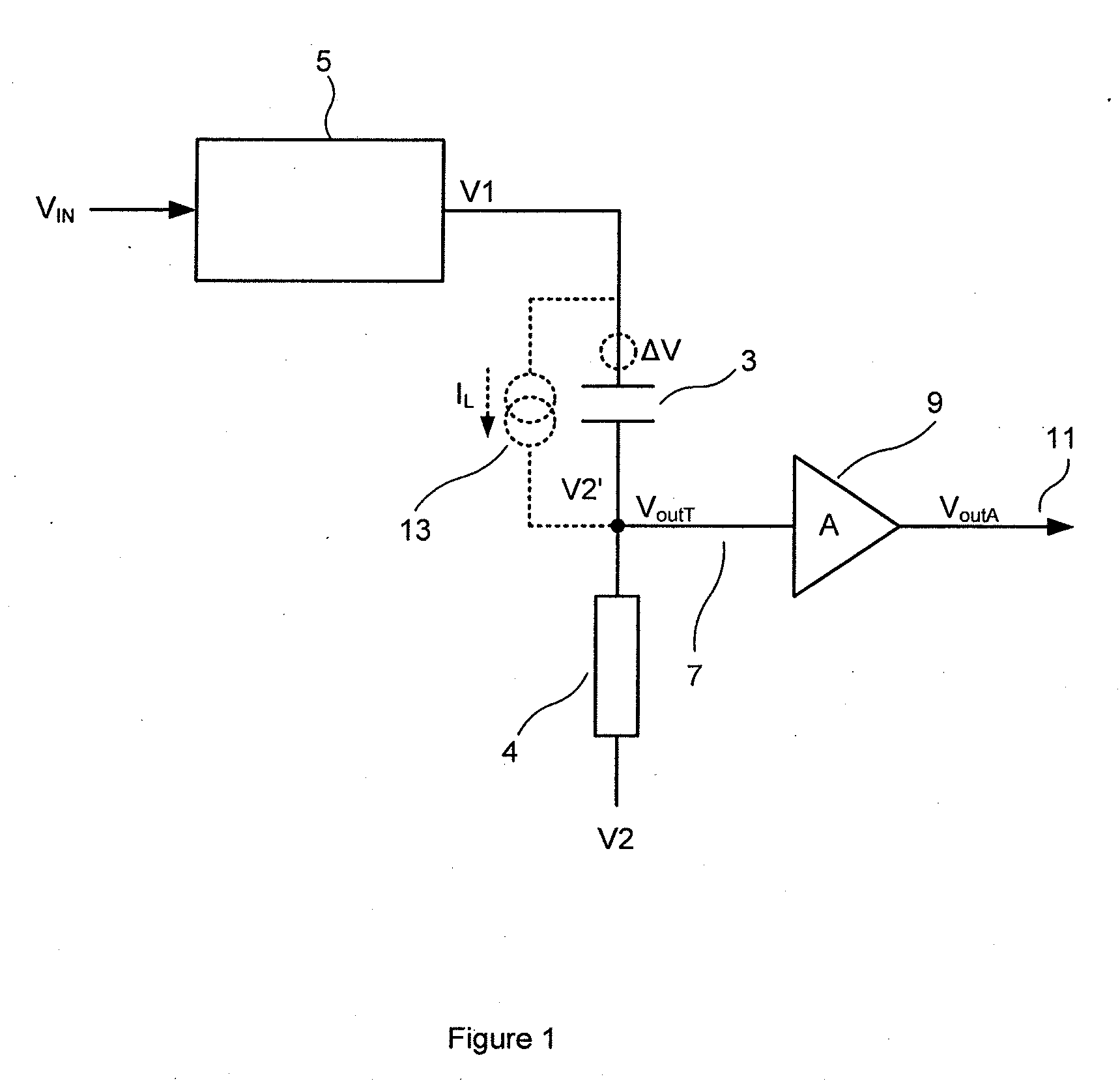
[0027]As described above, FIG. 1 shows a capacitive transducer 3 comprising a first electrode that is biased to a first bias voltage V1 supplied by a voltage source 5, and a second electrode that is connected to a node 7, the second electrode being biased to a second bias voltage V2′ via a high resistance 4. The voltage VoutT on node 7 is input to an amplifier 9, which outputs a corresponding voltage VoutA on an output terminal 11.
[0028]It is possible that significant and unpredictable leakage currents, for example as shown by IL, can appear on node 7. These, imposed on the high and variable resistance 4, result in a variable and significant offset and variability in the quiescent bias voltage of node 7. This variable offset may disturb the operating point of the amplifier and thus degrade its linearity, for instance causing the amplifier output to clip prematurely or to introduce distortion as its output approaches ground. It may also reduce the available dynamic range of downstrea...
PUM
 Abstract
Description
Claims
Application Information