Bend-Insensitive Single-Mode Optical Fiber

a single-mode, insensitive technology, applied in the field of optical fiber transmission, can solve the problems of incompatible fiber commercially with some transmission systems, light differences in actual profiles, complex technology, etc., and achieve the effect of sufficient attenuation of lp11 mode and improved bending loss

Active Publication Date: 2009-11-12
DRAKA COMTEQ BV
View PDF99 Cites 125 Cited by
  • Summary
  • Abstract
  • Description
  • Claims
  • Application Information

AI Technical Summary

Benefits of technology

[0022]Accordingly, the present invention includes a fiber with a central core, an intermediate cladding, and a depressed trench that is surrounded by an external optical cladding. The refractive index profile improves the bending losses by a factor of ten relative to the constraints imposed by the G.657B recommendation, while retaining a mode field diameter compatible with the G.652 recommendation and ensuring a sufficient attenuation of the LP11 mode.
[0023]In particular, the surface of the core, as well as the surface and the volume of the depressed trench, are designed to considerably improve the bending losses. In the context of the present invention, the surface of the core or the surface of the depressed trench should not extend geometrically but should correspond to values taking into account two dimensions—the product of the radius and the refractive index difference. Similarly, the volume of the depressed trench corresponds to a value taking into account three dimensions—the product of the square of the radius and the refractive index difference.
[0026]According to one fiber embodiment, the surface integral of the central core (V01), defined asV01=∫0r1Δn(r)·r≈r1×Δn1,is between about 19.0×10⁻³ micron and 23.0×10⁻³ micron, typically between about 20.0×10⁻³ micron and 23.0×10⁻³ micron. In another embodiment, the surface integral of the central core (V01) is between about 20.0×10⁻³ micron and 21.5×10⁻³ micron, which gives rise to outstanding optical properties.
[0027]According to another fiber embodiment, the surface integral of the depressed trench (V03), defined asV03=∫r2r3Δn(r)·r≈(r3-r2)×Δn3,is between about −55.0×10⁻³ micron and −30.0×10⁻³ micron. In another embodiment, the surface integral of the depressed trench (V03) is between about −42.5×10⁻³ micron and −32.5×0-3 micron, which gives rise to outstanding optical properties.
[0028]According to yet another fiber embodiment, the volume integral of the depressed trench (V13), defined as,V13=2·∫r2r3Δn(r)·r·r≈(r32-r22)×Δn3,is between about −1200×10−3 μm2 and −750×10−3 μm2. In another embodiment, the volume integral of the depressed trench (V13) is between about −1000×10−3 μm2 and −750×10−3 μm2, which gives rise to outstanding optical properties.
[0030]The fiber disclosed herein also shows reduced bending losses at higher wavelengths. For example, at a wavelength of 1625 nanometers, the fiber has bending losses less than about 10−2 dB / turn, typically less than about 1.5×10⁻³ dB / turn, for a radius of curvature of 15 millimeters, bending losses less than or equal to about 0.1 dB / turn, typically less than or equal to about 25×10−3 dB / turn, for a radius of curvature of 10 millimeters, bending losses less than or equal to about 0.15 dB / turn, typically less than or equal to about 0.08 dB / turn, for a radius of curvature of 7.5 millimeters, and bending losses less than or equal to about 0.25 dB / turn for a radius of curvature of 5 millimeters.

Problems solved by technology

Fiber manufacturing constraints may lead to a slightly different profile in the actual fiber.
Reducing the mode field diameter and / or increasing the effective cut-off wavelength reduces the MAC value but may lead to noncompliance with the G.652 recommendation, making the fiber commercially incompatible with some transmission systems.
The reduction of the bending losses, while retaining certain optical transmission parameters, constitutes a challenge for Fiber-To-The-Home (FTTH) applications.
Hole-assisted fiber technology makes it possible to achieve excellent performances with respect to bending losses, but this technology is complex and expensive to implement and cannot be used for fibers intended for low-cost FTTH systems.

Method used


Image

  • Bend-Insensitive Single-Mode Optical Fiber
  • Bend-Insensitive Single-Mode Optical Fiber
  • Bend-Insensitive Single-Mode Optical Fiber

Examples


Embodiment Construction

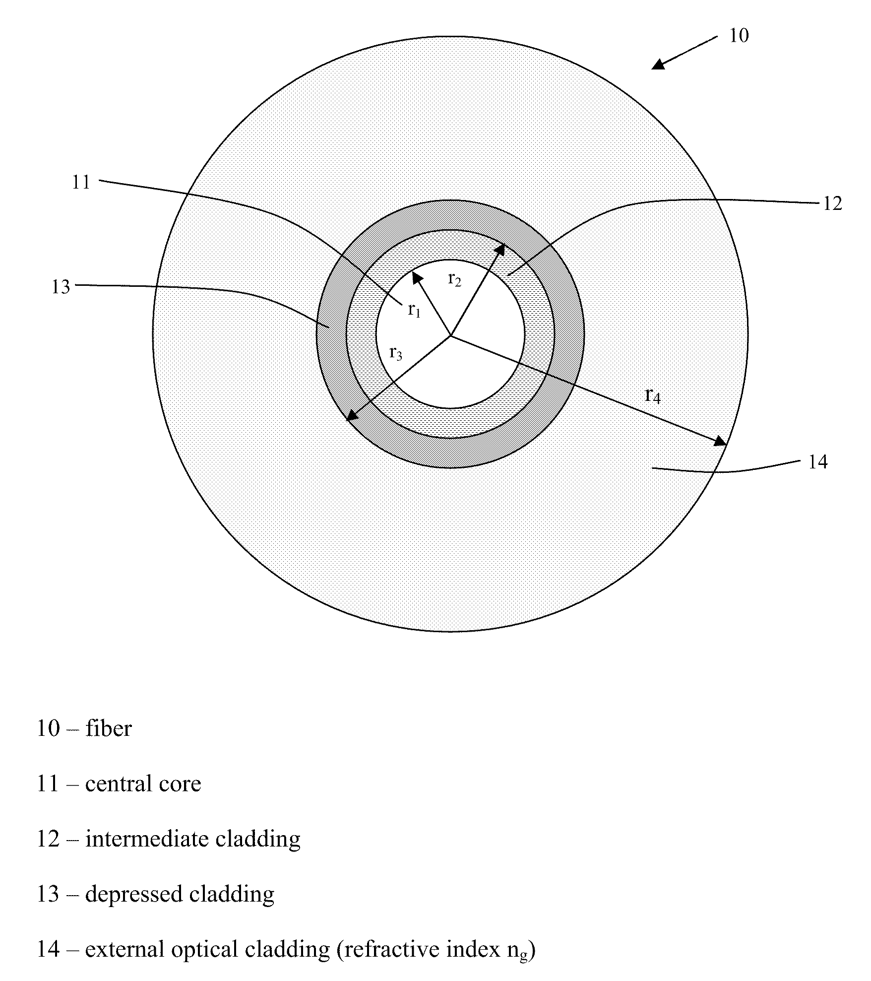
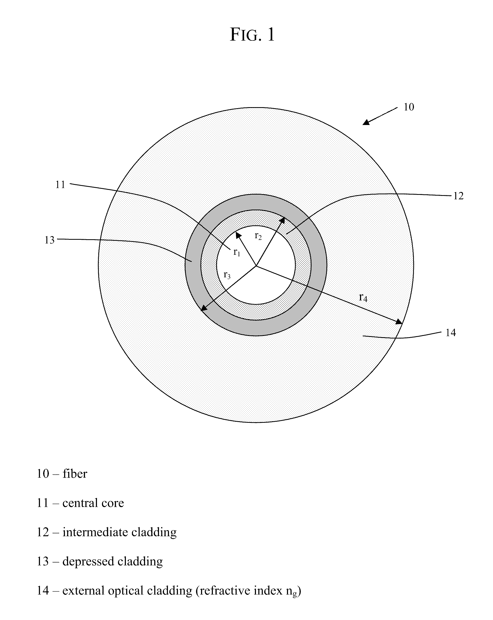
[0039]As depicted in FIG. 1, the optical fiber (10) of the invention has a central core (11), an intermediate cladding (12), and a depressed cladding (13). For purposes herein and without limiting the scope of the invention, depressed cladding means a radial portion of the fiber (10) having a refractive index less than the refractive index of the external optical cladding (14). Typically, the central core (11), the intermediate cladding (12), and the depressed cladding (13) are obtained by chemical vapor deposition in a silica tube. The external optical cladding (14) includes the silica tube and the overcladding on the tube. In exemplary embodiments, the overcladding is generally natural or doped silica, but can also be obtained by any other deposition technique (e.g., vapor axial deposition (“VAD”) or outside vapor deposition (“OVD”)).

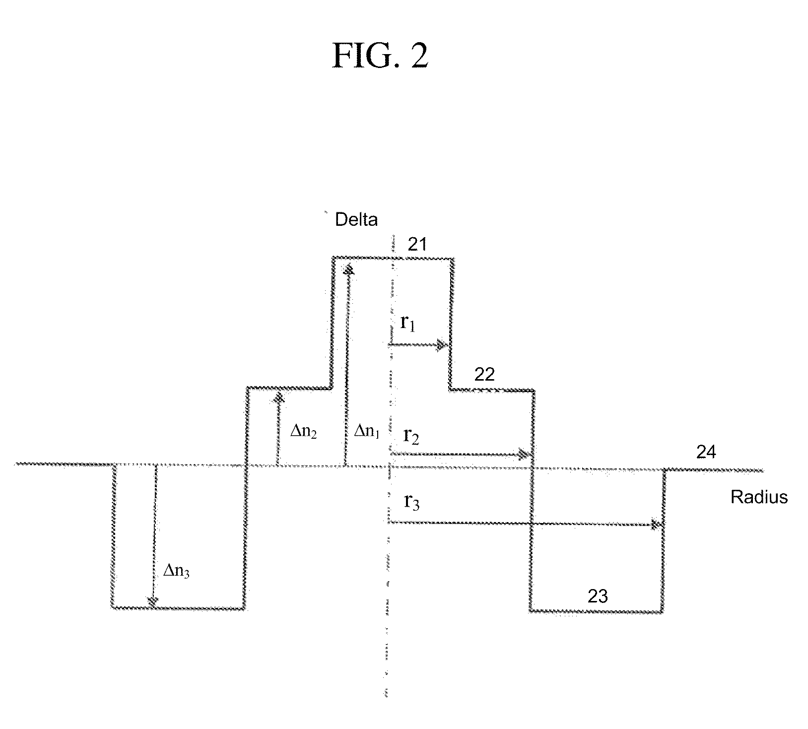
[0040]FIG. 2 illustrates a refractive index profile for the optical fiber (10) of FIG. 1. The profile of FIG. 2 is a set profile (i.e., representativ...


PUM


Abstract

A single-mode optical fiber includes a central core, an intermediate cladding, a depressed trench, and an external optical cladding. The central core has a radius r1 and a positive refractive index difference Δn1 with the optical cladding. The intermediate cladding has a radius r2 and a refractive index difference Δn2 with the optical cladding, wherein Δn2 is less than the central core's refractive index difference Δn1. The depressed trench has a radius r3 and a negative index difference Δn3 with the optical cladding. The optical fiber has a nominal mode field diameter (MFD) between 8.6 microns and 9.5 microns at a wavelength of nanometers, and at a wavelength of 1550 nanometers, the optical fiber has bending losses less than 0.15 dB / turn for a radius of curvature of 5 millimeters and cable cut-off wavelengths of less than or equal to nanometers.

Description

CROSS-REFERENCE TO PRIORITY APPLICATIONS[0001]This application claims the benefit of pending French application Ser. No. 08 / 02503 for “Fibre Optique Monomode” (filed May 6, 2008, at the French Patent Office), which is hereby incorporated by reference in its entirety.[0002]This application further claims the benefit of U.S. Patent Application No. 61 / 101,337 for a “Bend-Insensitive Optical Fiber” (filed Sep. 30, 2008), U.S. Patent Application No. 61 / 112,006 for a “Bend-Insensitive Single-Mode Optical Fiber” (filed Nov. 6, 2008), and U.S. Patent Application No. 61 / 112,374 for a “Bend-Insensitive Single-Mode Optical Fiber” (filed Nov. 7, 2008), each of which is incorporated by reference in their entirety.FIELD OF THE INVENTION[0003]The present invention relates to the field of optical fiber transmissions, and more specifically, to an optical fiber having greatly reduced bending losses.BACKGROUND OF THE INVENTION[0004]For optical fibers, the refractive index profile is generally set fort...

Claims


Application Information

Patent Timeline
Patent Type & Authority Applications(United States)
IPC IPC(8): G02B6/036
CPCG02B6/02266G02B6/02395G02B6/0365G02B6/028G02B6/036
Inventor DE MONTMORILLON, LOUIS-ANNERICHARD, SIMONMOLIN, DENISBOIVIN, DAVIDBIGOT-ASTRUC, MARIANNESILLARD, PIERRE
Owner DRAKA COMTEQ BV
Why Eureka
Try Eureka