
Adsorption heat pump with heat accumulator

a heat accumulator and heat pump technology, applied in the direction of heat storage plants, energy-efficient heating/cooling, sustainable buildings, etc., can solve the problems of marked conflict of objectives, steep gradient, and the amount of heat to be supplied by reheating is minimized

Inactive Publication Date: 2009-11-19
FRAUNHOFER GESELLSCHAFT ZUR FOERDERUNG DER ANGEWANDTEN FORSCHUNG EV
View PDF9 Cites 7 Cited by
  • Summary
  • Abstract
  • Description
  • Claims
  • Application Information

AI Technical Summary

Benefits of technology

[0026]A particularly suitable heat accumulator results when the heat accumulator is embodied as a container that can be filled or is filled with a liquid heat transfer medium, in particular water or water-containing mixtures, with a temperature-dependent density. In this manner a temperature stratification in the accumulator is achieved through the temperature-dependency of the density. A stratified accumulator known in the prior art is thus realized. It is also possible thereby to store the heat transfer medium used to transport the heat, directly in the heat accumulator. This removes the necessity of the transfer of the heat from one heat transfer medium to another. The production of entropy is thus avoided.
[0048]When a sorption accumulator is used as a heat source, the production of entropy can be reduced. To this end the sorption accumulator is to be operated as a heat source such that several modules of the sorption accumulator are discharged in a parallel manner such that they are located in different adsorption states and heat can be removed from the module furthest desorbed at a higher temperature level than from the already further adsorbed module, and that it is switched over in the course of a desorption phase of the heat pump between the different accumulator modules as driving heat source.

Problems solved by technology

The main disadvantage of the “thermal wave” is that the temperature gradient must be very steep for a significant increase of the COP, so that, e.g., during the largest possible part of the adsorption phase, the heat transfer fluid leaves the adsorber at the maximum adsorption temperature (and the amount of heat to be supplied by reheating is minimized).
However, a steep temperature gradient also means that only a small part of the adsorber is active (i.e., adsorbs) at any time and the major part of the adsorber has either already completely adsorbed or has not yet started the adsorption.
With the “thermal wave” there is therefore a marked conflict of objectives between the objectives of a high COP and of a high power density.
Furthermore, with the “thermal wave” the entire adsorber must be flowed through serially, which results in long paths for the heat transfer fluid and thus high pressure losses and pump energy consumption.
These problems may also have contributed to the fact that in the twenty years since the patent application of Shelton (U.S. Pat. No. 4,694,659) no adsorption heat pump or adsorption refrigeration machine has been brought on the market that realizes the principle of the “thermal wave.”
The main disadvantage of arrangements with heat recovery between more than two adsorbers is the high expenditure in terms of equipment that is to be operated for the adsorbers (to be thermally insulated from one another) and their changing interconnections.
The achievable COP increases here with the number of adsorbers, at the same time, however, the expenditure in terms of equipment rises and thus the cost of the refrigeration machine / heat pump.
Unfortunately, this improvement in the power density is first obtained at the cost of a reduction of the COP.
With an unfavorable sorptive / sensible heat ratio, such as can be expected for systems that render possible a high power density, increased efforts to increase the COP are therefore necessary.
According to their purpose of the stratification of heat from solar collectors and provision of heat for heating and domestic water, however, these accumulators do not contain any devices for temperature-controlled removal of fluid from selectable accumulator height.

Method used


Image

  • Adsorption heat pump with heat accumulator
  • Adsorption heat pump with heat accumulator

Examples


Embodiment Construction

[0051]Without restricting the generality, the invention, in particular the arrangement of the components of the heat pump system according to the invention, is described below in more detail.

[0052]They show:

[0053]FIG. 1 The desorption heat to be supplied and the released adsorption heat for an adsorber with the pair of substances SAPO-34 / water, which is operated in the cycle of an adsorption refrigeration machine under conditions which are typical for solar-supported building cooling: maximum desorption temperature 95° C., recooling and minimal adsorber temperature 35° C., evaporator temperature 15° C.

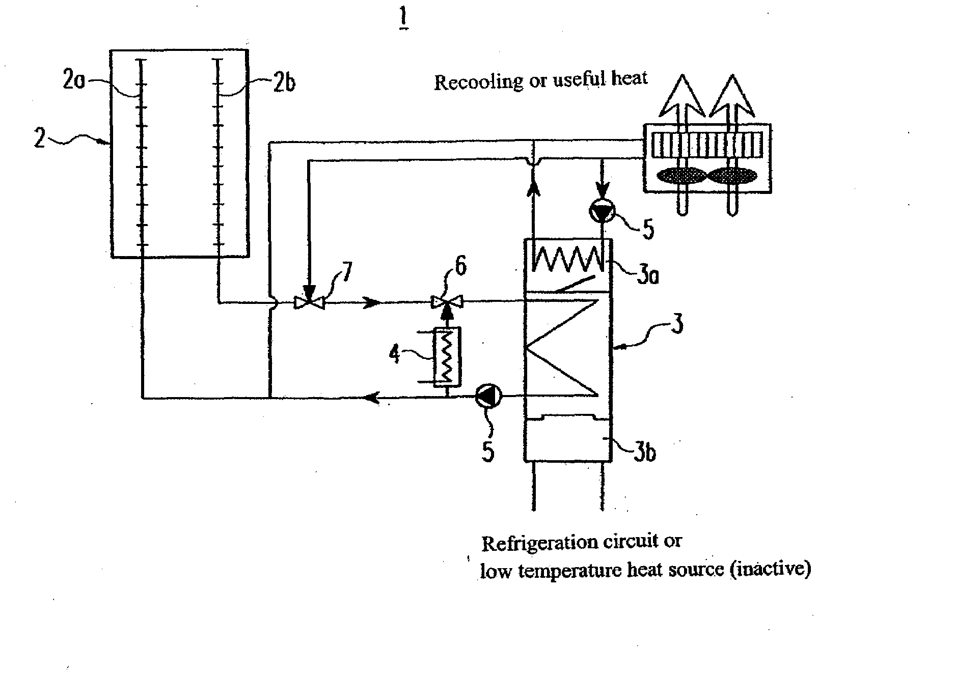
[0054]FIG. 2 A possible hydraulic interconnection of the components in the heat pump system according to the invention

[0055]These curves calculated from the adsorption equilibria of the pair of substances show which amount of heat must be supplied to the adsorber at which temperature for the desorption and how much heat can be extracted from the adsorber during the adsorption at which ...


PUM


Abstract

The invention relates to an arrangement that has an adsorption heat pump with at least one adsorber and at least one heat accumulator with the following features: heat at different temperature levels can be stored in the heat accumulator (2) simultaneously; adsorption heat released during the adsorption, which heat is not to be used for a later desorption, can be dissipated to a heat sink; adsorption heat that is to be used for the desorption can be stored in the heat accumulator at a temperature dependent on the adsorption temperature; desorption heat can be extracted at least in part from the heat accumulator at a desired temperature; a heat source, in particular a thermal solar collector is available, with which heat necessary for the desorption can be provided at a temperature level that is higher than the temperature levels achievable through previous desorption in the heat accumulator (2), and / or heat can be provided which is not available in the required quantity in the heat accumulator. The invention also relates to an associated method for operating an adsorption heat pump.

Description

TECHNICAL FIELD[0001]The invention relates to an adsorption heat pump or an adsorption refrigeration machine and a heat accumulator suitable for efficient operation.PRIOR ART[0002]The COP (Coefficient of Performance), i.e., the ratio of useful heat or useful cold to required driving heat, of adsorption refrigeration machines and adsorption heat pumps is typically lower than that of corresponding absorption plants under identical cycle conditions. A thermodynamic analysis (e.g., Meunier et al. 1996, 1997, 1998) shows that this lies in the adsorption above all at the entropy production, which occurs with a coupling of the adsorber to the heat sources and heat sinks of fixed temperature.[0003]This is illustrated by the example of the refrigeration machine: the temperature of the adsorber fluctuates in the course of the cycle between the highest available desorption temperature and the lowest adsorption temperature at which the adsorption heat can still be emitted to the environment (re...

Claims


Application Information

Patent Timeline
Patent Type & Authority Applications(United States)
IPC IPC(8): F25B17/00F25B27/00
CPCF25B17/08F25B27/007F25B2400/24Y02E70/30F28D20/0039Y02B30/64Y02E60/142F28D20/003Y02A30/27Y02B30/00Y02E60/14
Inventor MUNZ, GUNTHERSCHMIDT, FERDINANDNUNEZ, TOMASSCHNABEL, LENA
Owner FRAUNHOFER GESELLSCHAFT ZUR FOERDERUNG DER ANGEWANDTEN FORSCHUNG EV
Features
  • Generate Ideas
  • Intellectual Property
  • Life Sciences
  • Materials
  • Tech Scout
  • Unparalleled Data Quality
  • Higher Quality Content
  • 60% Fewer Hallucinations
Learn More