Fuel filter assembly with pressure sending unit

a technology of fuel filter and pressure sending unit, which is applied in the direction of liquid fuel feeder, machines/engines, instruments, etc., can solve the problems of fuel pump and injector wear, excessive wear and failure, and appreciable engine performance drop,

Inactive Publication Date: 2009-11-19
WILLISON WILLIAM L
View PDF42 Cites 20 Cited by
  • Summary
  • Abstract
  • Description
  • Claims
  • Application Information

AI Technical Summary

Problems solved by technology

Unfiltered fuel may contain several kinds of contamination, for example wax, asphaltines, or solid contaminants (e.g. paint chips and dirt that has been knocked into the tank while filling, or rust caused by moisture in a steel tank).
If these substances are not removed before the fuel enters the system, they will cause rapid wear and failure of the fuel pump and injectors, due to the abrasive action of the particles on the high-precision components used in modern injection systems.
If a filter is not cleaned or replaced regularly it may become clogged with contaminants and cause a restriction in the fuel flow, which causes an appreciable drop in engine performance as the engine struggles to draw enough fuel to continue running normally.
It is especially undesirable for water to be drawn into a diesel engine fuel system, as the system relies on the diesel fuel for lubrication of the moving parts, and if water gets into a moving part which requires constant lubrication (for example an injector valve), it will quickly cause overheating and unnecessary wear.
Also, because diesel engines require large amounts of compression to operate, water in the fuel system can be very dangerous as water cannot be compressed and may cause considerable engine damage.
Similarly, clogged injectors may allow the corresponding cylinder to run dry and damage the engine (e.g. burn a hole in the piston, melt the piston, or seize the engine).
For example, if a factory installed fuel filter becomes clogged on engines, the injector pump will suck contaminants through their filters and deposition of these same contaminants may occur in the injectors.
This results in either the injectors being clogged or stuck open.
When the injectors are stuck open, the engine will either be very difficult to start or will not start.
Clogged filters may allow the corresponding cylinder to run dry and can lead to engine damage such as a hole in a piston or a melted piston.
Either of these situations are costly to the vehicle owner / operator.
If the pistons are damaged the repair cost may be increased an additional range of about $12,000.

Method used


Image

  • Fuel filter assembly with pressure sending unit
  • Fuel filter assembly with pressure sending unit
  • Fuel filter assembly with pressure sending unit

Examples


example 1

[0038]A diesel engine is an internal combustion engine which operates using the Diesel cycle. These engines were invented in 1892 by German engineer Rudolf Diesel, it was

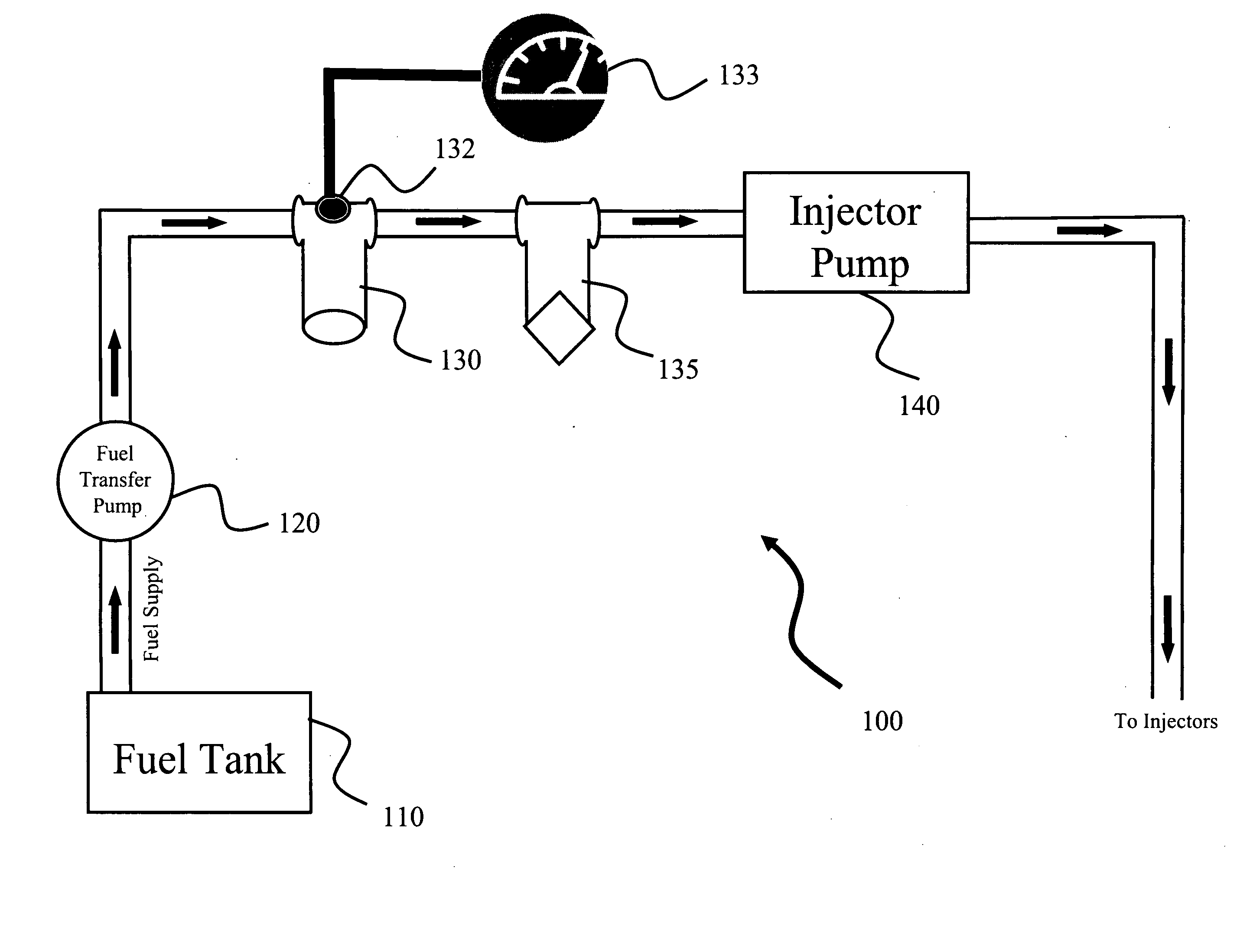
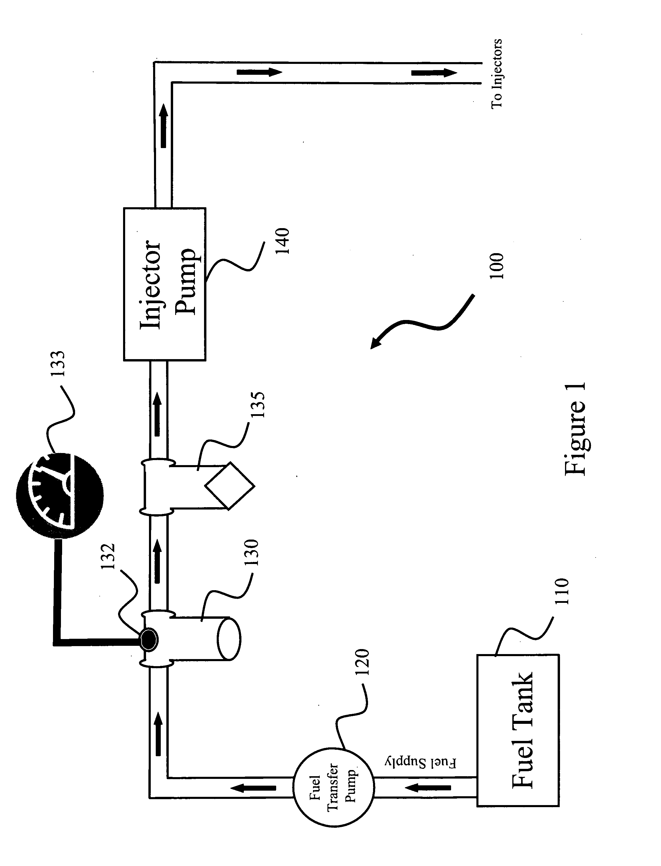
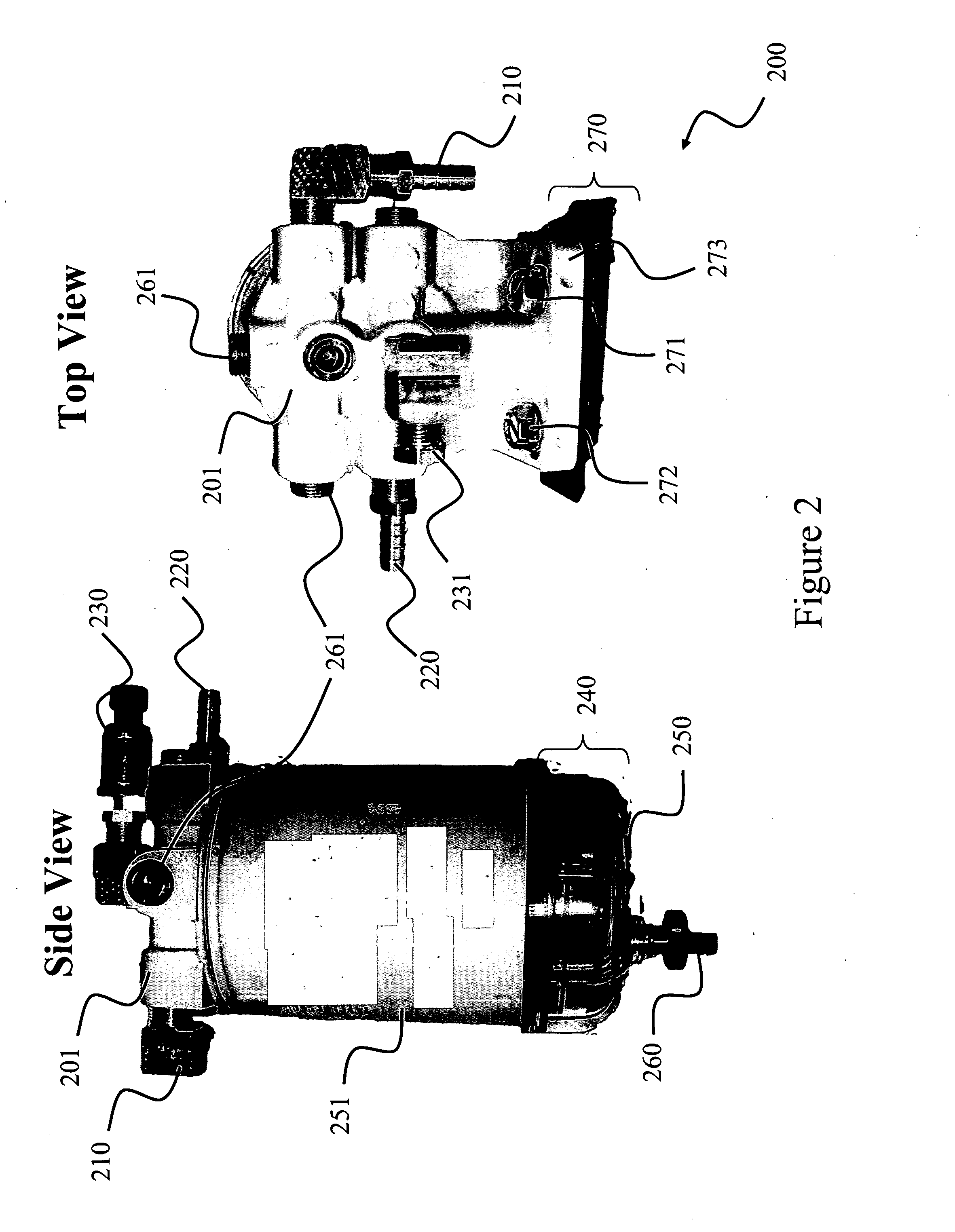
[0039]A 2003 Dodge Diesel Pickup was used to test the ability of the instant invention to monitor fuel pressure during engine operation. The general fuel supply system for the 2003 Dodge diesel comprised a fuel tank, a fuel transfer pump, an OEM fuel filter, injection pump that feeds into a plurality of injectors. One embodiment of the invention comprises a 2 micron Racor-Parker fuel filter (Part No. R60S) and an Autometer 4360 sending unit and pressure gauge, as shown in FIG. 2 and FIG. 3. As shown in the figure the fuel pressure gauge sending unit is mounted in one of the filters outlet ports. The sending unit leads to a fuel pressure gauge mounted, preferably in the drivers side “A” pillar of the cab of the vehicle. One reason for mounting the gauge in this position is to make it as visible as possible to the dri...

example 2

[0042]One of ordinary skill in the art understands vehicles having engines other than ones found in Example 1 experience similar problems with clogged fuel filters that cause costly engine malfunctions. As such, the instant invention can be modified for different engines designs. Although each engine's needs vary to a certain extent, modifications are within the spirit and scope of the instant invention.

[0043]Vacuum Fuel Supply: There are at least two manufactures that utilize a vacuum fuel supply system and a 2 micron final filter on their current production engines (i.e. GM and Isuzu). Although not wanting to be bound by theory, one modification would be to utilize a vacuum gauge, wherein, the vacuum gage sensor could be mounted in the supply line between the final filter and the engine. For the GM and Isuzu example, the max vacuum is about 12″ of Hg. Similarly, highway diesel trucks can utilize a mounting design that is similar to the GM / Isuzu model, but the max vacuum will vary ...

example 3

[0045]A tractor is a vehicle specifically designed to deliver a high tractive effort at slow speeds, for the purposes of hauling a trailer or machinery used in agriculture or construction. Most commonly, the term is used to describe the distinctive farm vehicle: agricultural implements may be towed behind or mounted on the tractor, and the tractor may also provide a source of power if the implement is mechanized. Another common use of the term, “tractor unit”, describes the power unit of a semi-trailer truck, tractors, agriculture, and industrial equipment. As such, some of these machines use pressure fuel supply systems and some use vacuum. Most of this equipment appears to have sufficient filter quality, so additional filters may not be required. However, the pressure sender or the vacuum source should be mounted after the secondary filter and the pressure or vacuum.


PUM


Abstract

A fuel filter assembly having a pressure sending unit for filtering and monitoring fuel and fuel pressure for diesel engines and the like comprising a filter head, a spin-on element and collection bowl. The filter head is fastened to an engine or other suitable structure by flange, bolts and supports the fuel filter assembly by monitoring fuel pressure by utilizing a pressure sending unit in fluid communication with an outlet port on the filter head. Preferably, filter head is a die cast head and includes therein typical inlet port, outlet port, and connected respectively thereto, inlet chamber and outlet chamber. Filter head is a generally circular structure having a flat annular mounting surface. The filter head may further comprises vent ports, vacuum switch ports or both, which are in fluid communication with outlet ports and return check valve ports that are in fluid communication with inlet ports. Still further, filter head is in fluid communication with a pressure sending unit, which is in electrical communication with a pressure monitoring device or similar warning system.

Description

RELATED APPLICATIONS[0001]This application claims priority to U.S. Provisional Patent Application, Ser. No. 61 / 127,493, entitled “Fuel Filter Assembly with Pressure Sending Unit,” filed on May 15, 2008, the entire content of which is hereby incorporated by reference.FEDERALLY SPONSORED RESEARCH[0002]Not Applicable.JOINT RESEARCH AGREEMENTS[0003]Not Applicable.SEQUENCE LISTING[0004]Not Applicable.BACKGROUND OF THE INVENTION[0005]This invention generally relates to a fuel filter in combination with a pressure sending unit. More particularly, this invention relates to a fuel filter having a 2-5 micron filter in with a pressure sending unit that includes pressure sensing means therein for monitoring the condition of the fuel filter allowing a user to evaluate the buildup of residues and subsequent clogging of the fuel system filter. In a specific embodiment, the fuel filter in combination with a pressure sending unit is to be installed between the fuel transfer pump and the original man...

Claims


Application Information

Patent Timeline
Patent Type & Authority Applications(United States)
IPC IPC(8): F02B1/12F02M69/00G01M15/04F02M37/32
CPCF02M37/22G01M15/09F02M2037/226F02M37/46F02M37/32
Inventor WILLISON, WILLIAM L
Owner WILLISON WILLIAM L
Why Eureka
Try Eureka