Brush apparatus

a brush and holding device technology, applied in the direction of electrical devices, current collectors, dynamo-electric machines, etc., can solve the problems of shortening the life of the brush, voltage drop, lowering the strength lowering the stability of the holding member, so as to improve the electrical performance and reduce the cost

Active Publication Date: 2009-11-19
MITSUBISHI ELECTRIC CORP
View PDF7 Cites 6 Cited by
  • Summary
  • Abstract
  • Description
  • Claims
  • Application Information

AI Technical Summary

Benefits of technology

[0009]This arrangement enables to elongate the life of the brush, and to store the brush stably in the brush holder. Since the flexibility of the pigtail is sufficiently secured, the pigtail is prevented from hindering the contact between the brush and the commutator, which improves electrical performance. In addition, the pigtail may be formed of a general-purpose member, and may be connected to the brush holding member easily, so that cost reduction is expected.

Problems solved by technology

However, when the thickness of the lead wire increases, the finished outer diameter of the pigtail increases accordingly, and the dimensions of permissible wear from a surface of the brush, which comes into sliding contact with a commutator, to the lower end of a embedded portion of the pigtail decreases, which shortens the life of the brush.
However, the pigtail employing a thick lead wire has poor flexibility, which hinders the downward movement of the brush and causes a contact failure between the brush and the commutator, which may result in the voltage drop.
On the other hand, when two lead wires are embedded in the brush as shown in FIG. 4B in JP-A-2003-79093, since the positions where the two lead wires are embedded are different, the shape of a brush holder is constrained and hence a holding contact surface with respect to the brush decreases, which may result in lowering of the strength of the holding member and lowering of the holding stability.
Therefore, reduction of the brush height is necessary, and hence shortening of the brush life against the wear is unavoidable.

Method used


Image

  • Brush apparatus
  • Brush apparatus
  • Brush apparatus

Examples


Embodiment Construction

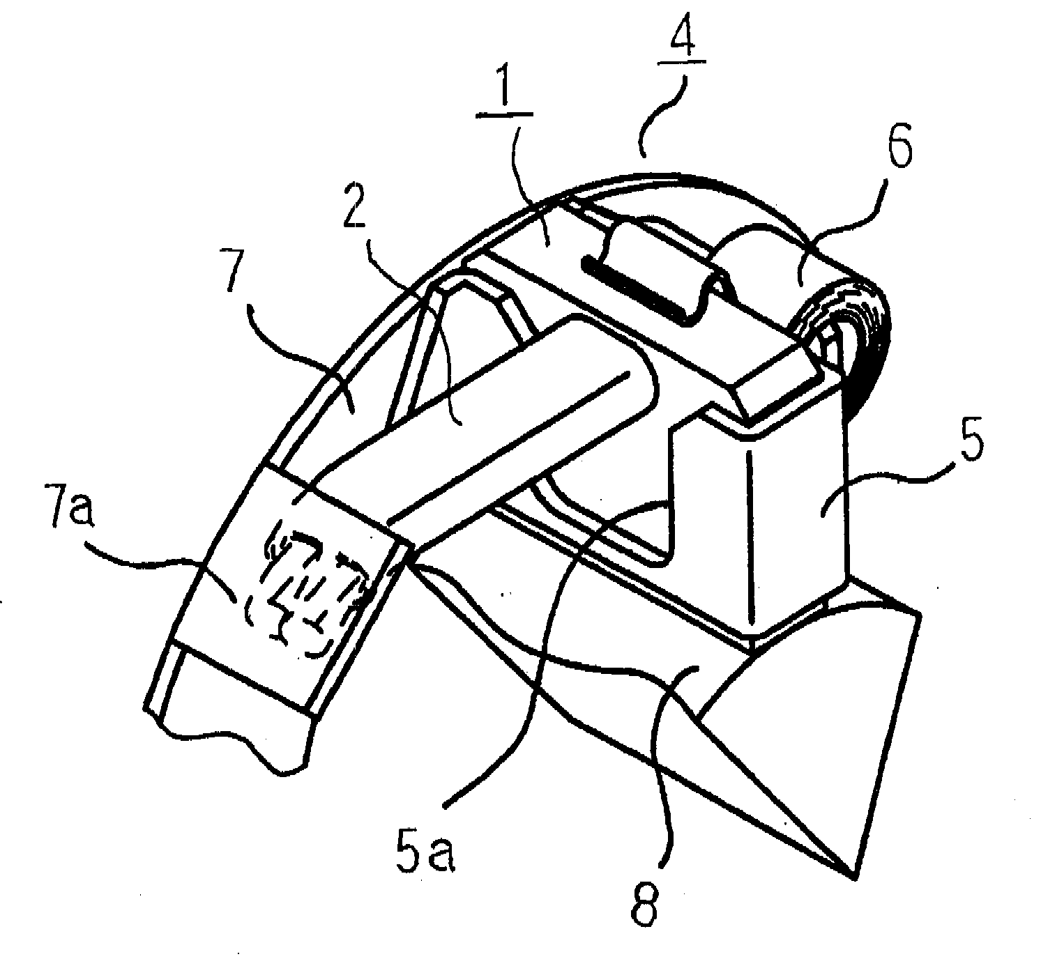
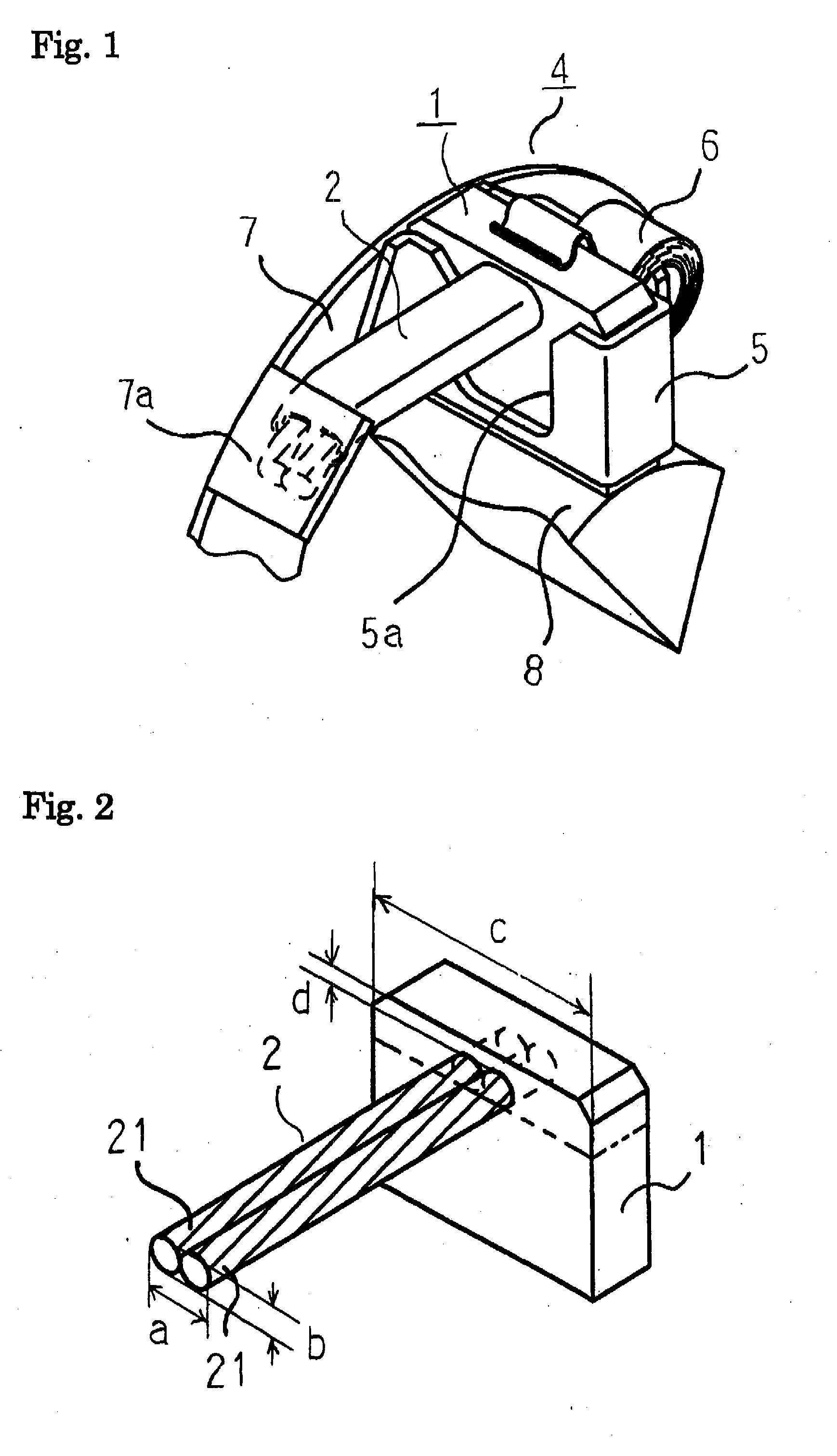
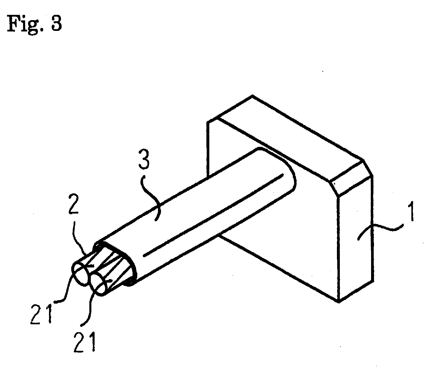
[0014]FIG. 1 is a perspective view illustrating part of a brush apparatus of an engine starter according to an embodiment of the invention; FIG. 2 is a perspective view illustrating a brush without an insulation tube according to the embodiment of the invention; and FIG. 3 is a perspective view illustrating the brush with the insulation tube according to the embodiment of the invention.

[0015]In FIG. 1, the brush apparatus in the invention includes a brush holder 4 and a brush 1. The brush holder 4 includes a brush holding member 5 having a tubular space formed into a rectangular shape in cross section when viewed from the top. One of narrower sides of the brush holding member 5 is fixed to a base 7. The brush 1 having a pigtail 2, described later, is inserted into the brush holding member 5, and the lower end of the brush 1 is in sliding contact with a commutator 8. A brush spring 6 formed by winding a thin plate, which applies an adequate contact pressure to the commutator 8 by pre...


PUM


Abstract

A brush apparatus includes a brush and a brush holder. The brush includes a pigtail embedded in a wider side thereof so that the longitudinal side in cross-section of the pigtail extends in parallel with a surface of the brush coming into contact with a commutator. The brush holder includes a brush holding member, a brush spring for pressing the brush against the commutator for sliding contact, a base for holding the brush holding member and electrically connecting the same to an earth circuit, and a connection lug on the base. The brush holding member is formed with a notch on a wider side from an upper end thereof for allowing a downward movement of the pigtail when the brush wears and hence is pressed downward. A distal end of the pigtail is connected to the connection lug.

Description

BACKGROUND OF THE INVENTION[0001]1. Field of the Invention[0002]The present invention relates to a brush apparatus used for, for example, an engine starter.[0003]2. Description of the Related Art[0004]In general, in order to achieve high-power and high-current in a direct current electric motor (DC electric motor) such as an engine starter, reduction of an internal electric resistance and upsizing of the electric motor are effective. As a measure for reducing the internal electric resistance, it is considered to increase a cross-sectional area of a conductor of a pigtail for the purpose of reduction of a current density and voltage drop of a lead wire which constitutes the pigtail. In order to do so, it is necessary to increase the thickness of the lead-wire or to connect a plurality of the lead wires to a brush disclosed, for example, in JP-A-11-178285 and JP-A-2003-79093.[0005]In order to increase the cross-sectional area of the conductor of the pigtail without changing the brush ...

Claims


Application Information

Patent Timeline
Patent Type & Authority Applications(United States)
IPC IPC(8): H01R39/40
CPCH01R39/381H01R39/36
Inventor KANEDA, NAOHITOKAMEI, KOICHIRO
Owner MITSUBISHI ELECTRIC CORP
Why Eureka
Try Eureka