Phase current measurements in a three phase inverter using a single common dc-link current sensor

a three-phase inverter and phase current technology, applied in the direction of ac-dc conversion, automatic controllers, synchronous motor starters, etc., can solve the problems of more complex and no longer present conditions to measure phase current with a single common dc-link sensing resistor, and achieve the effect of sufficient duration

Active Publication Date: 2009-11-19
STMICROELECTRONICS SRL
View PDF6 Cites 57 Cited by
  • Summary
  • Abstract
  • Description
  • Claims
  • Application Information

AI Technical Summary

Benefits of technology

[0011]In view of the foregoing background, an object of the present invention is to provide a method for measuring current in each phase of a three phase inverter driven motor, controlled in a PWM mode by three PWM signals. This and other objects, advantages and features in accordance with the present invention is provided by a method using a relatively straightforward determination of the modulation index for the voltage demand set by the motor controller, specific mutual duty cycle conditions of the three PWM phase driving signals and by a consequent choice of the way “sampling windows” of sufficient duration for allowing to sample distinctly two phase currents are provided for optimal performance.

Problems solved by technology

Unfortunately, these enabling conditions may no longer be present under unfavorable duty cycle conditions of the PWM signals and special techniques for creating “sampling windows” of adequate duration for allowing distinct sampling of at least two of the three phase currents during a PWM period have been disclosed.
By enhancing the output voltage level compared to conventionally known sinusoidal drive waveform pulse width modulation schemes, these new modulation techniques make it even more complex to measure phase currents with a single common DC-link sensing resistor.

Method used


Image

  • Phase current measurements in a three phase inverter using a single common dc-link current sensor
  • Phase current measurements in a three phase inverter using a single common dc-link current sensor
  • Phase current measurements in a three phase inverter using a single common dc-link current sensor

Examples


Embodiment Construction

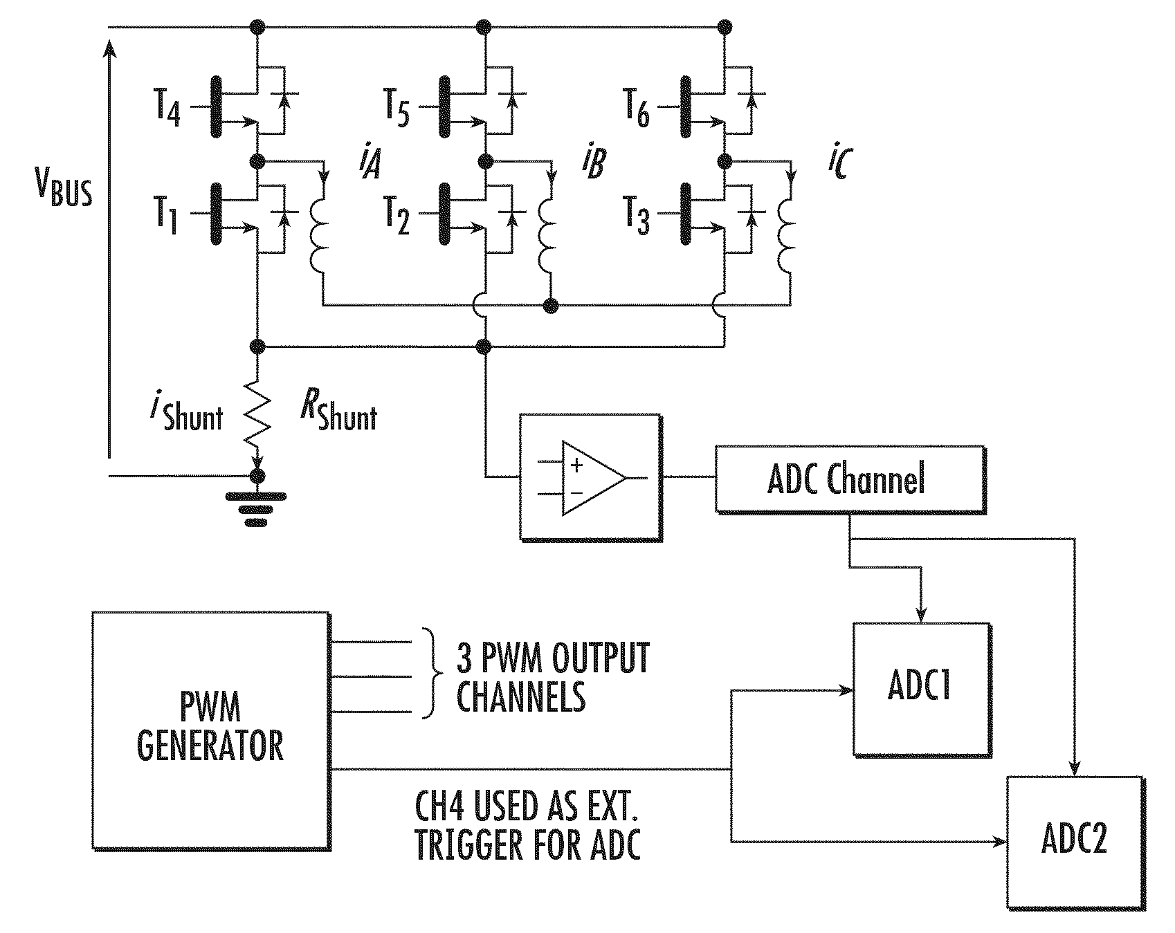
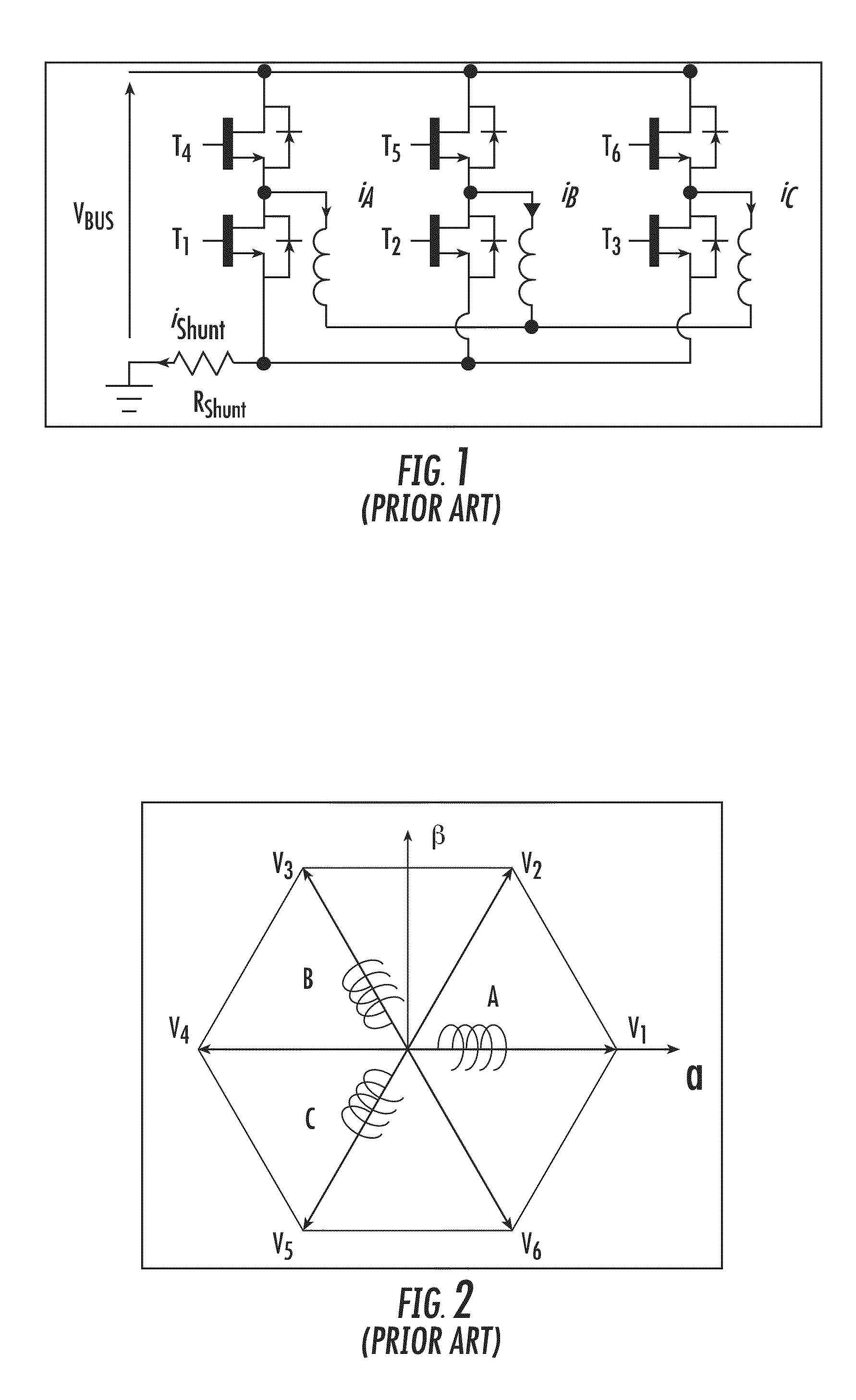
[0043]A classical three-phase inverter bridge includes of six power switches T1, T2, T3, T4, T5, T6 is shown in FIG. 1. The three inductors driven by the respective half bridges (or bridge legs) represent the three phase windings constituting the stator of the motor, in which the phase currents iA, iB and iC flows. A single common current sensing resistor Rshunt connected in the DC-link allows sensing the DC current ishunt that is absorbed from the power supply bus at the supply voltage Vbus. Phase currents are assumed positive when flowing from the inverter output nodes to the windings, the DC current ishunt is assumed positive when flowing toward the common ground node of the circuit.

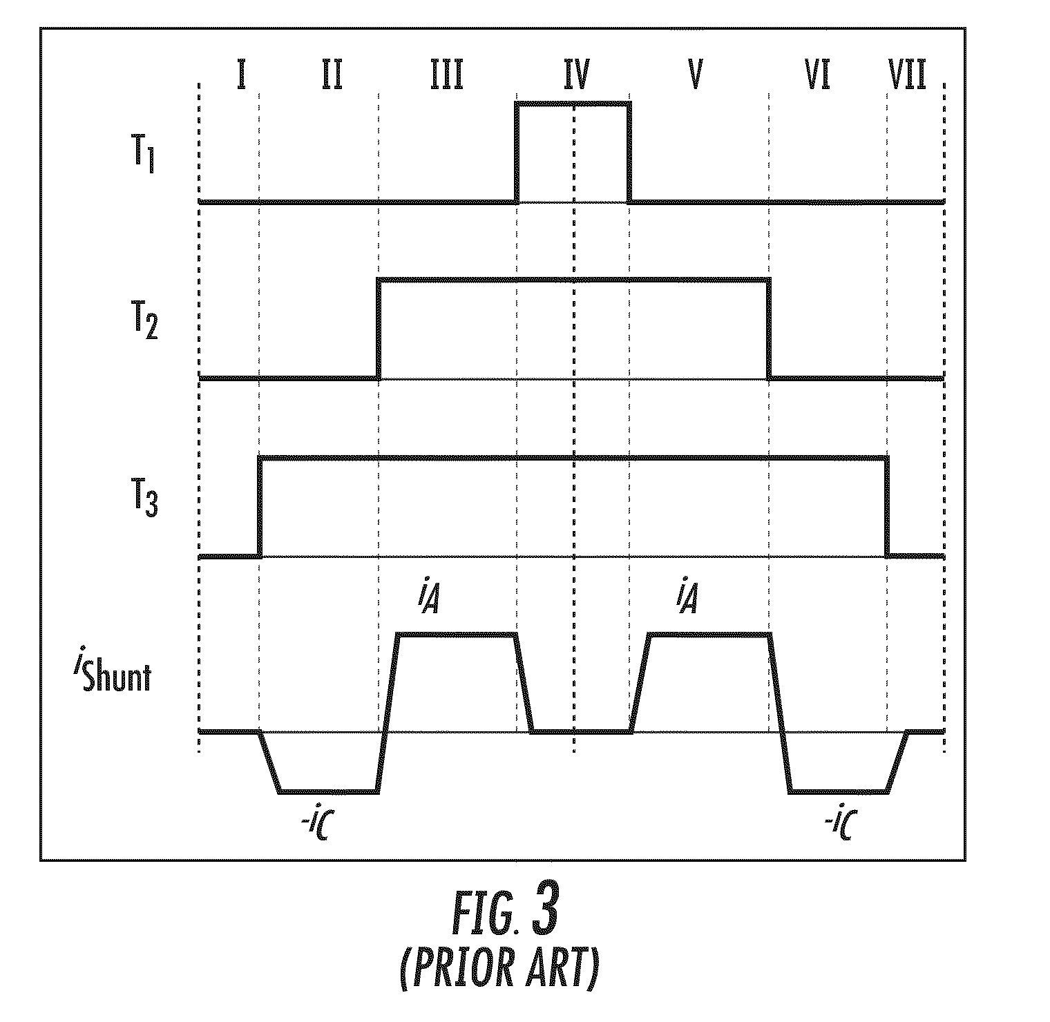
[0044]According to common practice, complementary PWM signals control the high side and the low side switches of each leg of the three-phase bridge, necessarily with dead time insertions to exclude risks of simultaneous turned-on states of the two switches of the three legs of the inverter bridge that...


PUM


Abstract

A method for measuring current in each phase of a three-phase inverter driven motor is based on the three-phase inverter being controlled in a PWM mode by three PWM signals including the use of a common DC-link current sensing resistor. The current on the sensing resistor is intermittently sampled. The method includes determining a modulation index for the voltage demand set by a motor controller. Based on specific mutual duty cycle conditions of the three PWM phase driving signals, sampling windows of sufficient duration are created for allowing distinct sampling of two of the phase currents.

Description

FIELD OF THE INVENTION[0001]This invention relates in general to three-phase power devices, for example, a three-phase permanent magnet synchronous motor or induction motor driving inverters, and, in particular, to an improved method of distinctly measuring phase currents using a single common direct current link current sensor.BACKGROUND OF THE INVENTION[0002]The phase windings of a three-phase motor may be controlled using pulse width modulated (PWM) signals. Typically, the PWM control signals are applied to a three-phase inverter. The switching devices of the three-phase inverter connect the phase winding taps of the motor to either a positive or a negative power supply voltage rail and to ground.[0003]For proper control of the motor, it is typical to measure the current flowing through each phase winding. The phase current measurements are provided to a controller that generates the PWM drive signals that control the switching devices of the three-phase inverter. Traditionally, ...

Claims


Application Information

Patent Timeline
Patent Type & Authority Applications(United States)
IPC IPC(8): H02P21/00
CPCH02M2001/0009H02M7/53871H02M1/0009
Inventor FORTE, GIANLUGI
Owner STMICROELECTRONICS SRL
Why Eureka
Try Eureka