Hydraulically Driven Conveyor

Inactive Publication Date: 2009-11-19
ULTRA TRANSFER SYST
View PDF18 Cites 9 Cited by
  • Summary
  • Abstract
  • Description
  • Claims
  • Application Information

AI Technical Summary

Benefits of technology

[0013]The residual feed pick-up system of this invention utilizes a trailer that includes a blower for the pneumatic conveyor mounted on the trailer rather than the tractor. Additionally, the technique for motivating the blower is hydraulic rather than mechanical. Thus feed pick-up service provided by the novel trailer avoids the operational expense of having to provide a customized, very costly tractor dedicated exclusively for pick-up service. Also, because hydraulic power operates the trailer-mounted blower, a hydraulic power supply unit which is usually a standard feature or very common accessory of many commercial over-the-road tractors can be utilized to drive the blower without radical vehicle customization. Moreover, bulk feed delivery tractors which pull cargo tank trailers of poultry feed to growers usually already have hydraulic power supply units that

Problems solved by technology

Feeding the animals is, of course, a critical aspect of the operation and it can involve the transfer of very large quantities of food.
This feed is not suitable for the incoming chicks.
This conventional feed pick-up system has commercially significant drawbacks.
Firstly, existing tractors with pick-up capability are more expensive to outfit than standard tractors.
This can contributes substantially to the cost of the tractor because the mechanical link is an specially added tractor feature.
Secondly, conventional feed pick-up vehicles create certain logistical problems for the supplier.
This is because these tractors are more expensive than standard tractors and the relatively low volume of feed pick-up service compared to normal feed delivery service does not justify having more than a few, minimally essential units in the fleet.
However, pick-ups can occur at difficult to predict times and must meet the needs of the growers' schedules.
This can lead to supp

Method used


Image

  • Hydraulically Driven Conveyor
  • Hydraulically Driven Conveyor
  • Hydraulically Driven Conveyor

Examples


Embodiment Construction

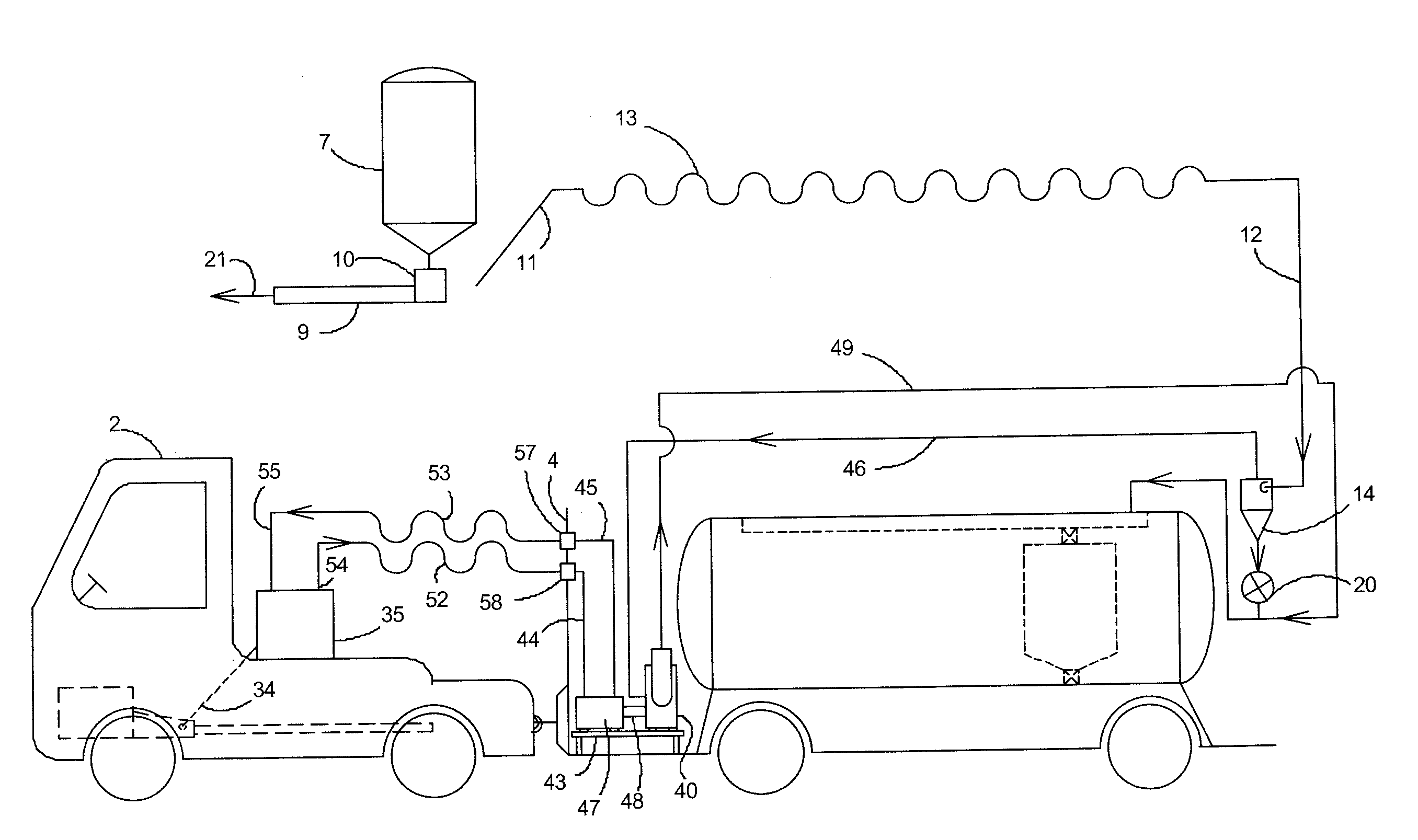
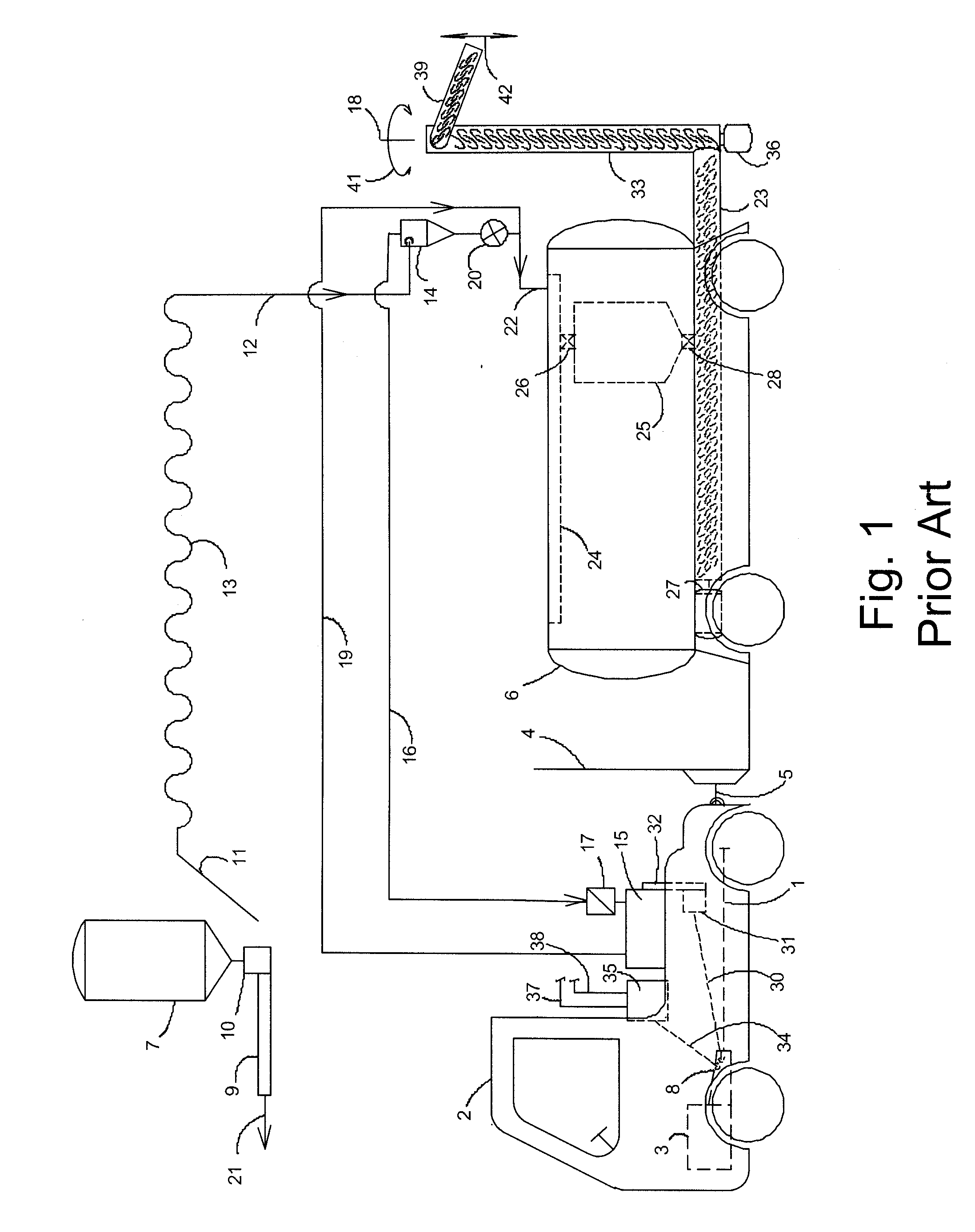
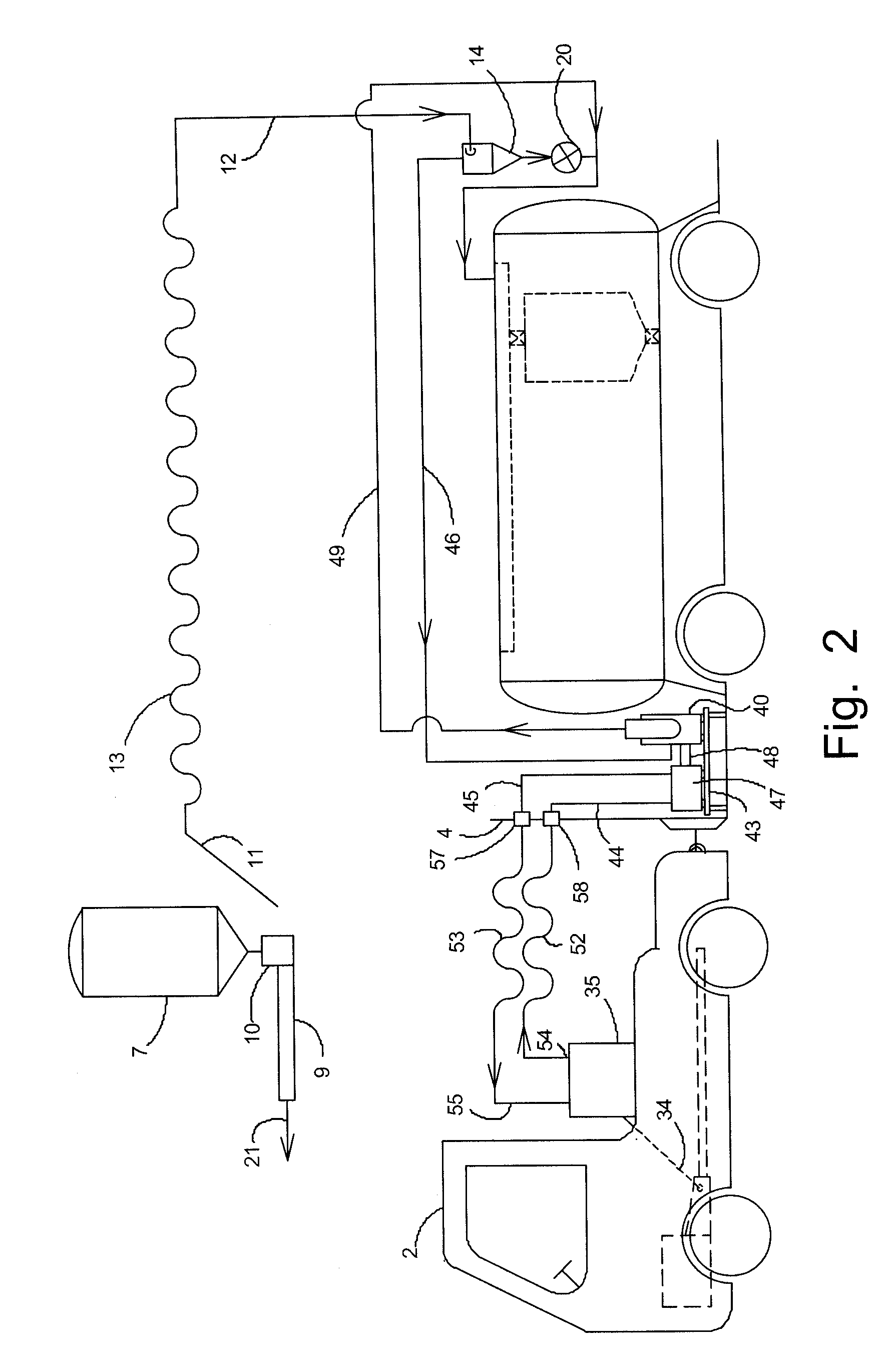
[0020]The present invention can be understood by comparison to a typical conventional residual feed pick-up system according to the prior art illustrated in FIG. 1. This system includes an over-the-road tractor 2 shown coupled by hitch 5 to a mobile cargo trailer 4 on which is positioned a tank 6 intended to receive and contain for transport residual feed picked up from a poultry farm. The residual feed is to be removed from storage bin 7. The feed is taken from the bin by blower 15 via transfer line 12. Direction of material flow in the drawings is shown by arrows. Blower 15 is mounted on tractor 2.

[0021]As illustrated, the residual feed in bin 7 awaits picking up. Normally while the poultry house is occupied by birds, the feed from this bin is gravity fed to solids conveyor 9. This conveyor typically includes an elongated screw rotating in a long, narrow trough. The screw is usually driven by an electric motor. The feed 21 is thus moved into the poultry house where it feeds the bi...


PUM


Abstract

An residual feed pick-up system for poultry farming utilizes a tractor and trailer combination in which the blower for a pneumatic conveyor is mounted on the trailer. The hydraulic motor that drives the blower is also located on the trailer. Feed pick-up can be effected by the trailer accompanied by a standard over-the-road tractor equipped with a conventional and economically available hydraulic power takeoff unit commonly known as a PTO. The feed supplier to the poultry farm can use any of such commonly configured tractors in its normal operating fleet combined with the trailer having the onboard hydraulically driven blower for low-volume, residual feed pick-up service, thereby increasing reliability and availability of the service at advantageously low cost.

Description

[0001]This application claims benefit of U.S. provisional patent application No. 60 / 759,414 filed Jan. 17, 2006.FIELD OF THE INVENTION[0002]This invention relates to bulk transfer of material via tank trailers between storage locations. More specifically it pertains to bulk transfer of granular poultry feed from numerous satellite storage tanks to a central supply depot using tank trailers equipped with hydraulically driven pneumatic conveyors.BACKGROUND OF THE INVENTION[0003]Large scale poultry farming involves raising vast numbers of birds, typically in a flock of thousands, living communally in fixed structure shelters, (“houses”). The flock remains together and does not move from a single house during nearly its entire growing cycle extending from the age of young chicks until harvesting as adults. Feeding the animals is, of course, a critical aspect of the operation and it can involve the transfer of very large quantities of food.[0004]The industry typically utilizes granular f...

Claims


Application Information

Patent Timeline
IPC IPC(8): B65G53/04B60P1/60
CPCB65G53/24B60P1/60
Inventor BROWN, WILLIAM
Owner ULTRA TRANSFER SYST
Why Eureka
Try Eureka