
Monomer for binding nano-metal, conductive polymer composite and method of preparing the conductive polymer composite

a polymer composite and nano-metal technology, applied in the direction of conductors, organic chemistry, transportation and packaging, etc., can solve the problems of decreasing electrical conductivity relative to similar polymer materials, reducing polymer solubility and light transmittance, etc., to achieve high conductivity, ensure transparency and flexibility, and high conductivity

Active Publication Date: 2009-11-19
SAMSUNG ELECTRONICS CO LTD
View PDF12 Cites 8 Cited by
  • Summary
  • Abstract
  • Description
  • Claims
  • Application Information

AI Technical Summary

Benefits of technology

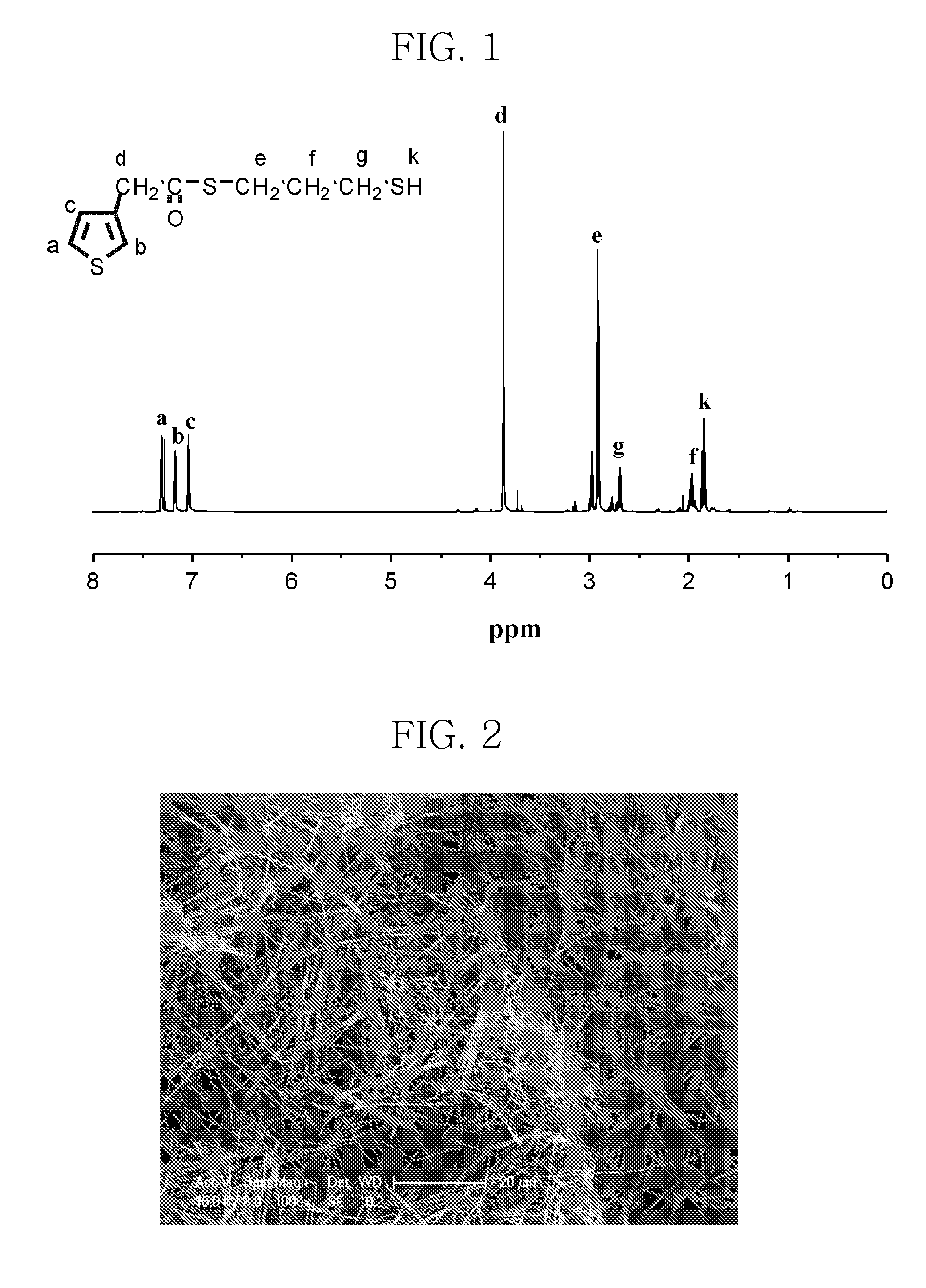
The patent text describes a need for conductive polymers that have high electrical conductivity, solubility, and light transmittance. The text describes a monomer that can bind to nano-metals, which can be used to create a conductive polymer composite with high conductivity, transparency, and flexibility. The monomer has a specific formula and can be attached to the surface of nano-metal rods. The method involves binding the monomer to the nano-metal rod, mixing it with conductive polymer monomers, a polymerization initiator, and a dopant, and then subjecting it to heating and polymerization. The technical effect of this patent is the creation of a new monomer that can be used to create conductive polymers with high conductivity, solubility, and light transmittance.

Problems solved by technology

Where conductive polymers are doped in order to impart electrical conductivity, drawbacks such as decreased polymer solubility and light transmittance may occur.
And, while the solubility of conductive polymers may be increased, electrical conductivity tends to decrease relative to similar polymer materials that are unmodified.

Method used


Image

  • Monomer for binding nano-metal, conductive polymer composite and method of preparing the conductive polymer composite
  • Monomer for binding nano-metal, conductive polymer composite and method of preparing the conductive polymer composite
  • Monomer for binding nano-metal, conductive polymer composite and method of preparing the conductive polymer composite

Examples


experimental example 1

Measurement of Conductivity and Sheet Resistance

[0068]The conductive polymer composite (D) including the nano-gold rod obtained in Example and the comparative conductive polymer were measured for conductivity using a van der Pauw 4-point probe method, and the conductivity measured was used to calculate sheet resistance. The results are shown in Table 1 below.

experimental example 2

Measurement of Light Transmittance

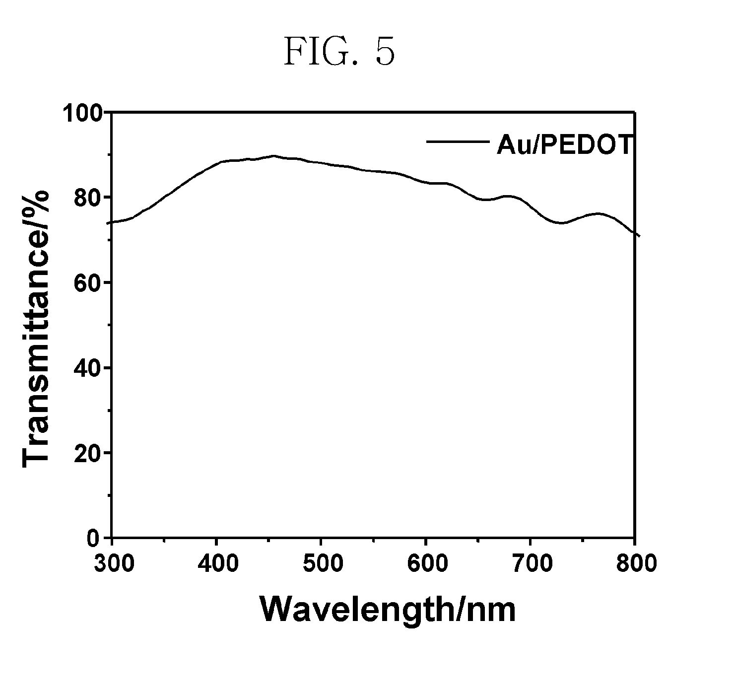
[0069]The conductive polymer composite (D) including the nano-gold rod obtained in Example and the comparative conductive polymer were measured for light transmittance at 550 nm using a UV-vis spectrophotometer. The results are shown in Table 1 and FIG. 5.

TABLE 1ConductivitySheet ResistanceLight Transmittance(S / cm)(Ω / square)(%)Example80010085C. Example35040085

[0070]As is apparent from Table 1 and FIG. 5, the conductivity of the conductive polymer composite (D) including the nano-gold rod (Example in Table 1) was determined to be 800 S / cm, which is much higher than that of the PEDOT (C. Example in Table 1). Further, light transmittance was maintained at 80% or higher, and sheet resistance decreased to a level of less than 200 Ω / square. Accordingly, the exemplary conductive polymer composite can substitute for conventional metal electrodes of various devices, unlike conventional conductive polymer material. The exemplary material is a polymer obtained...


PUM

PropertyMeasurementUnit
lengthaaaaaaaaaa
lengthaaaaaaaaaa
conductiveaaaaaaaaaa

Abstract

Disclosed herein is a monomer for binding nano-metal, which is useful for the preparation of a conductor having increased conductivity with ensuring flexibility and transparency. Polymerization of the monomer for binding nano-metal provides a conductive polymer composite including a nano-metal rod. A method of preparing the conductive polymer composite is also provided.

Description

[0001]This non-provisional application claims priority to Korean Patent Application No. 10-2008-0044482, filed on May 24, 2008, and all the benefits accruing therefrom under U.S.C. §119, the contents of which are incorporated herein by reference in their entirety.BACKGROUND[0002]1. Field[0003]This disclosure is directed to a monomer for binding nano-metal, a conductive polymer composite and a method of preparing the conductive polymer composite, and more particularly, to a monomer for binding nano-metal for use in the preparation of a conductive polymer composite including a nano-metal rod, to a conductive polymer composite, and to a method of preparing the conductive polymer composite.[0004]2. Description of the Related Art[0005]Conductive polymers generally have a π-conjugated structure, where such conductive polymers exhibit the properties of a conductor due to delocalization of electron density within the polymer chain from doping to create a delocalizable charge (positive or ne...

Claims


Application Information

Patent Timeline
Patent Type & Authority Applications(United States)
IPC IPC(8): B32B15/08C08G75/00B05D3/00
CPCY10T428/294H01B1/22C07D333/22H01B1/127B82Y30/00C07C211/46C07D207/02C07D307/64
Inventor SOHN, BYUNG HEELEE, YOUNG KWANYUN, YI YOIUNGJOO, WON JAE
Owner SAMSUNG ELECTRONICS CO LTD
Learn More