Starting and generating apparatus for engine

a technology of starting and generating apparatus, which is applied in the direction of electric generator control, gearing, dynamo-electric converter control, etc., can solve the problems of air-turbine starters being likely to malfunction, increasing the total weight, and increasing the cost, and achieves a small starting torque and smooth start.

Active Publication Date: 2009-11-19
KAWASAKI HEAVY IND LTD
View PDF17 Cites 44 Cited by
  • Summary
  • Abstract
  • Description
  • Claims
  • Application Information

AI Technical Summary

Benefits of technology

[0037]According to the starting and generating apparatus for the engine of this invention, the rotator can be started in a considerably light load state, in which the power transmission from the power transmission mechanism to the engine is shut off by the clutch mechanism. Therefore, the rotator can be started, while being directly supplied with electricity from a proper power supply, without any help provided by the power converter. After the rotator has been started and when the rotational speed of the rotator has reached the given value that can allow the engine to be started, the clutch mechanism is brought into the connected state so that the rotation of the rotator can be transmitted to the engine via the power transmission mechanism. As a result, ...

Problems solved by technology

However, in the case of using such generators, it is necessary to provide the engine starter separately from the generator.
Therefore, the use of such generators tends to increase the total weight and requires a relatively wide space, leading to increase of the cost.
In addition, such an air-turbine starter is likely to malfunction.
Especially, the compressed-air pipes increase the weight and require a considerably wide space for installment, thus raising the cost.
However, a brushless synchronous generator, which is commonly known as the generator used for the aircraft, cannot generate such large starting torque when used as the motor.
Meanwhile, a permanent magnet synchronous generator can generate such large starting torque, while the voltage cannot be well controlled.
Therefore, such a permanent magnet synchronous generator should require a p...

Method used


Image

  • Starting and generating apparatus for engine
  • Starting and generating apparatus for engine
  • Starting and generating apparatus for engine

Examples


Embodiment Construction

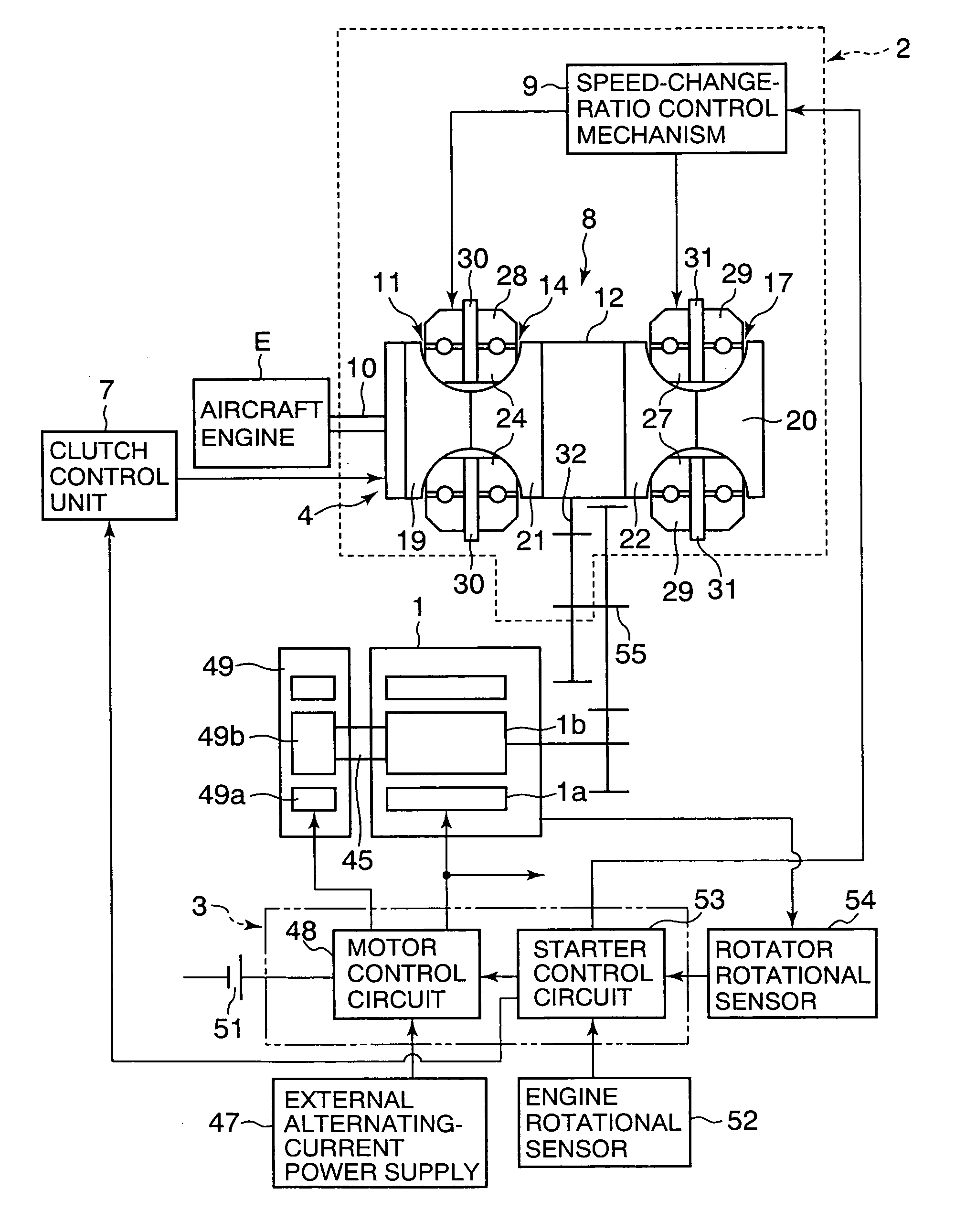
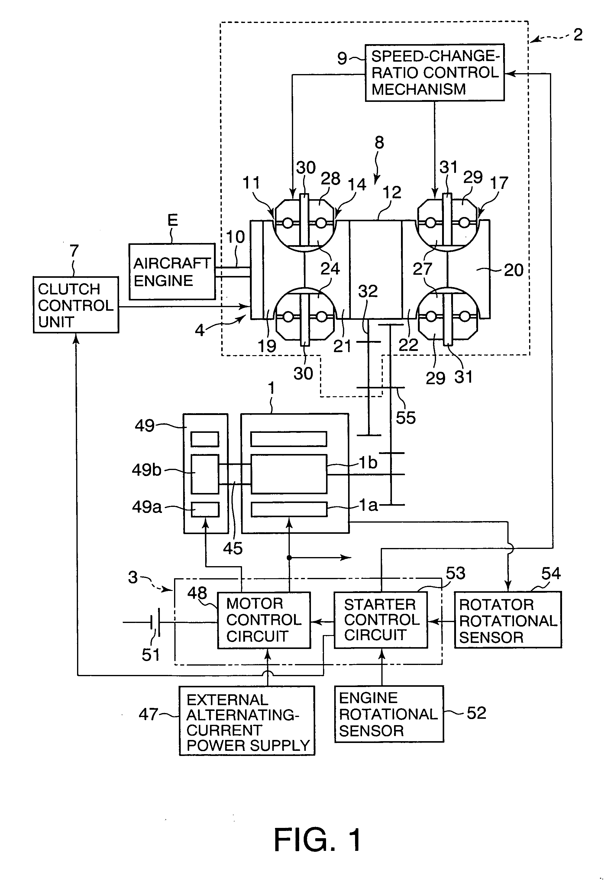
[0048]Referring to FIG. 1, the starting and generating apparatus according to the embodiment of the present invention includes a rotator 1 which can be used as an alternating-current generator driven by an aircraft engine E as well as a starter motor for starting the engine E. This apparatus also includes a power transmission mechanism 2 configured to connect the aircraft engine E with the rotator 1. A starter drive unit 3 configured to supply electricity to the rotator 1 is disposed in order to drive the rotator 1 as the starter motor when the aircraft engine E is started. The starter drive unit 3 is also configured to switch the operation of the rotator 1 from the starter motor to the generator when the rotational speed of the engine E has reached an idling rotational speed (i.e., a speed that can allow an independent operation) after the aircraft engine E has been started. This apparatus also includes a clutch mechanism 4 configured to shut off power transmission from the aircraf...


PUM


Abstract

The invention is a starting and generating apparatus for an engine, including: a rotator configured to be used as a generator driven by an engine as well as used as a starter motor for starting the engine; a power transmission mechanism configured to connect the engine with the rotator; a starter drive unit configured to supply an electricity to the rotator to drive the rotator as the starter motor when the engine is to be started; a clutch mechanism configured to shut off a power transmission from the engine to the power transmission mechanism when the engine is to be started; and a clutch control unit configured to bring the clutch mechanism into a connected state when a rotational speed of the rotator has reached a given rotational speed at which the engine can be started.

Description

CROSS REFERENCE TO RELATED APPLICATIONS[0001]This application is based upon the prior Japanese Patent Application No. 2008-126235 filed on May 13, 2008, the entire contents of which are incorporated herein by reference.BACKGROUND OF THE INVENTION[0002]1. Field of the Invention[0003]The present invention relates to a starting and generating apparatus for an engine, which is adapted for starting an engine by using a rotator, as well as for generating electricity by driving the rotator at a constant rotational speed with the output of rotation of the engine which has been brought into an independently operated state after started by the rotator.[0004]2. Description of the Related Art[0005]Conventionally, in a large-sized aircraft, an air-turbine type starter utilizing compressed air has been predominantly used as an engine starter. For such an air-turbine type starter, it is necessary to provide an APU (Auxiliary Power Unit), or compressed-air pipe, valves and the like, between the eng...

Claims


Application Information

Patent Timeline
IPC IPC(8): F02N11/08H02K7/20
CPCF02D2400/12F02N11/04F02N15/025Y10T477/71F02N2300/104F16H15/38F16H61/6649F02N15/043
Inventor TANAKA, KENICHIROGOI, TATSUHIKOSUGIMOTO, KAZUSHIGENAKAMURA, MASAHIDEHIROTA, YASUTAKAWATANABE, KOJI
Owner KAWASAKI HEAVY IND LTD
Why Eureka
Try Eureka