
Idling rotation speed control apparatus

a control apparatus and rotation speed technology, applied in the direction of electrical control, instruments, vessel construction, etc., can solve the problems of large number of setting data pieces in the ecu (electronic control unit), difficulty in performing a minute throttle operation, and large number of man-hours for matching, so as to reduce the cost

Active Publication Date: 2009-11-19
MITSUBISHI ELECTRIC CORP
View PDF4 Cites 6 Cited by
  • Summary
  • Abstract
  • Description
  • Claims
  • Application Information

AI Technical Summary

Benefits of technology

[0009]The present invention has been implemented in order to solve the foregoing problems; the objective of the present invention is to provide an idling rotation speed control apparatus, for a boat, in which development man-hours and the cost can be reduced, waterman's operation during a trolling cruise can readily be performed, and the respective rotation speeds during an idling state with no load (a neutral state) and during an idling state with a load can be controlled so as to become target values.
[0011]According to the preset invention, while an engine is in an idling state, matching data can be set with a torque ratio, regardless of a shift-lever position and a trolling speed, and because, in calculating a supply air amount, differences in a target rotation speed, an ignition timing, an engine capacity, and the like are automatically compensated, matching setting can readily be performed. Moreover, the control logic can be simplified, the development man-hours can be reduced, and the matching data can universally be utilized in other engines. Still moreover, the load on a waterman during a trolling cruise can be reduced, the trolling rotation speed can accurately be controlled, and transition between a trolling state and a neutral state can be smoothened; therefore, there can be provided an idling rotation speed control apparatus, for a boat engine, that has a higher accuracy.

Problems solved by technology

In some cases, pitching or rolling (or both) of a boat makes it difficult to perform a minute throttle operation; accordingly, for example, Japanese Patent Laid-Open No. 1999-218046 has proposed a control device in which an external resistor is made to perform a function of adjusting the rotation speed of the engine during a trolling cruise so that the amount of air is controlled only during a trolling cruise.
Because a boat engine is utilized in such a trolling cruise as described above, the load imposed on the engine in an idling state largely changes and the target rotation speed differs, depending on a driving condition; therefore, in order to control the rotation speed by directly increasing or decreasing air amount data when the idling rotation speed of an outboard engine is controlled, the number of setting data pieces in an ECU (Electronic Control Unit) becomes large, and a great number of man-hours for matching are required.
Additionally, also in the case where the rotation speed is controlled by feeding back an air amount in accordance with the difference between the target rotation speed and an actual rotation speed, the control program becomes extremely complicated, because setting of the feedback gain differs depending on the target rotation speed or the load imposed on the engine when the engine operates.
Additionally, in the case where a specification such as an engine capacity differs, massive data is required for each engine.
As described above, in the case where a high-accuracy idling rotation speed control apparatus for an outboard engine is configured, massive man-hours are required and matching data cannot universally be utilized; therefore, setting has been required for each engine.

Method used


Image

  • Idling rotation speed control apparatus
  • Idling rotation speed control apparatus
  • Idling rotation speed control apparatus

Examples


embodiment 1

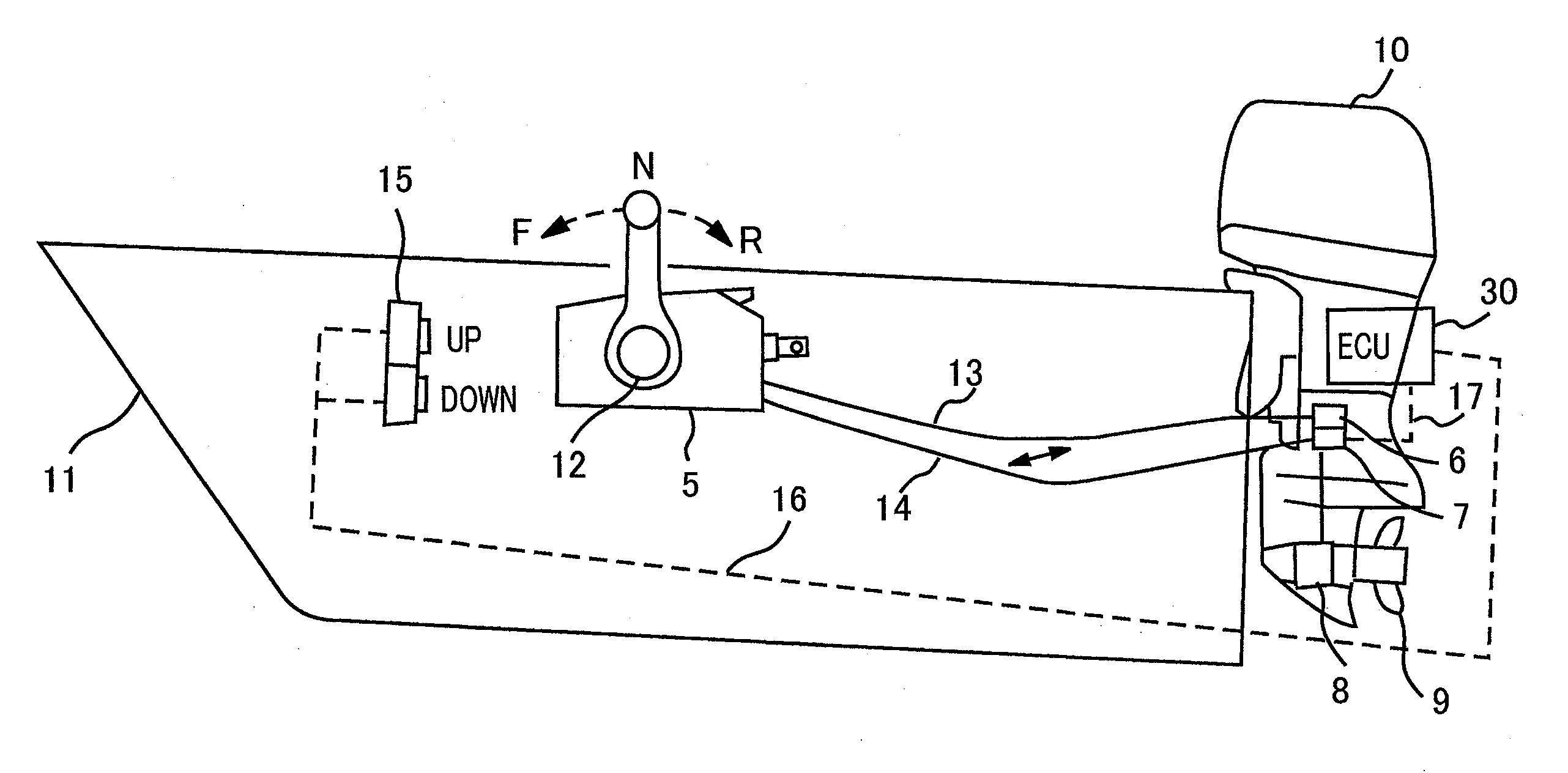
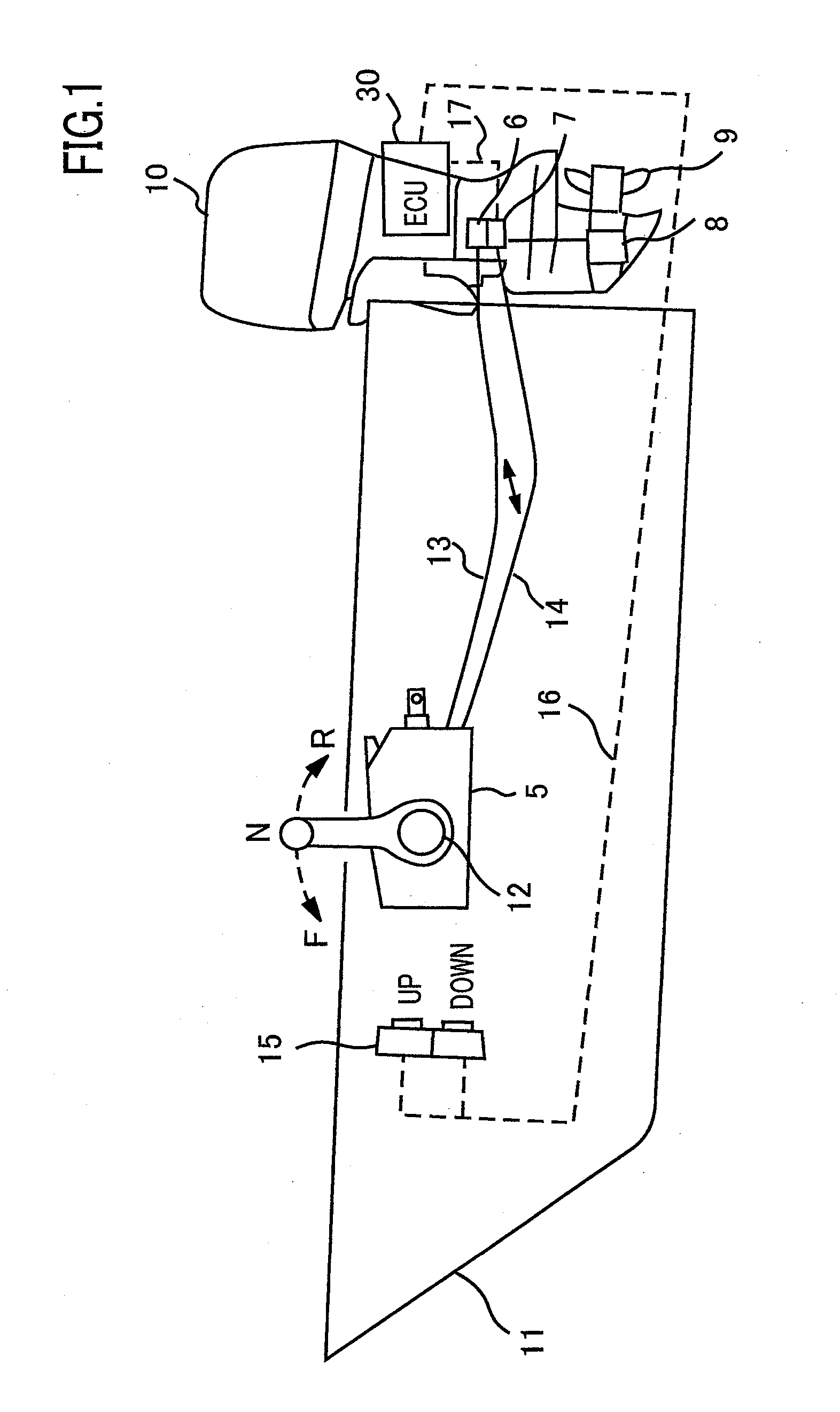
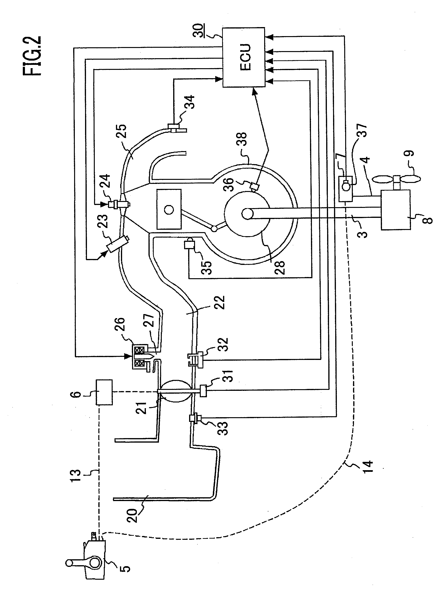
[0038]FIG. 1 is a schematic diagram illustrating a boat to which the present invention is applied. An outboard engine 10 is a propulsion engine in which an internal combustion engine (referred to as an engine, hereinafter), a propeller shaft, a propeller, and the like are integrated; the outboard engine 10 is mounted at the stern of a boat 11. A remote controller 5, which is manipulated by a driver, is provided at the right side of the cockpit, and propulsive force and a propulsive direction can be set by use of a throttle lever 12. The throttle valve opening amount (TH) (intake air amount) is adjusted by use of the remote controller 5 via a throttle cable 13 and a throttle link mechanism 6 in the outboard engine 10. The shift-lever position (the neutral position N, the forward position F, or the backward position R) is set by use of the remote controller 5 via a shift cable 14 and a shift link mechanism 7 and a gear mechanism 8 that are disposed in the outboard engine 10. Informati...


PUM


Abstract

There is provided an idling rotation speed control apparatus that can reduce the development man-hours and the cost and that enables operation during a trolling cruise to be readily performed. The idling rotation speed control apparatus includes an engine rotation speed detection means, an engine temperature detection means, an engine idling driving state detection means, an engine load detection means, an intake air amount adjusting means for adjusting an amount of intake air during an idling state, and an ECU for controlling the intake air amount adjusting means during idling driving. The ECU includes a basic torque ratio calculation function for calculating a ratio of torque to be generated, to engine maximal torque, that is necessary for making the engine steadily operate at a target rotation speed during idling driving; a target torque ratio calculation function for correcting the basic torque ratio, in accordance with a difference between a target rotation speed and an engine rotation speed, and calculating a target torque ratio; a target air amount calculation function for calculating an air amount necessary for generating the target torque ratio; and an intake air amount adjusting function for controlling the intake air amount adjusting means, based on the calculated air amount.

Description

BACKGROUND OF THE INVENTION[0001]1. Field of the Invention[0002]The present invention relates to an idling rotation speed control apparatus for controlling, when an internal combustion engine is idled, the rotation speed of the engine mounted on a ship or a boat.[0003]2. Description of the Related Art[0004]With regard to an electronically controlled engine, as disclosed, for example, in Japanese Patent Publication No. 1995-33797, an idling rotation speed control method has been proposed in which the amount of air supplied to the engine in an idling state is controlled so that the rotation speed of the engine is controlled to be a predetermined value. However, it is necessary for a small boat such as a motorboat or a fishing boat to perform a trolling cruise in which the boat cruises at a constant speed that is within a low-speed range close to an idling state; therefore, in general, it is necessary for a waterman to perform a minute throttle operation. In some cases, pitching or rol...

Claims


Application Information

Patent Timeline
Patent Type & Authority Applications(United States)
IPC IPC(8): F02D45/00
CPCF02D31/003F02D2200/023F02D41/16F02D31/005
Inventor ISHIDA, YASUHIKOSAKO, HITOSHI
Owner MITSUBISHI ELECTRIC CORP
Learn More