
Plan execution control apparatus, plan execution control method, and plan execution control program

a technology of plan execution control and control apparatus, applied in the direction of electric programme control, pulse technique, instruments, etc., can solve the problems of limited number of maintenance personnel, difficult to maintain installations located in a wide area, and large time-consuming to restore the installations

Inactive Publication Date: 2009-11-19
HITACHI LTD
View PDF25 Cites 13 Cited by
  • Summary
  • Abstract
  • Description
  • Claims
  • Application Information

AI Technical Summary

Benefits of technology

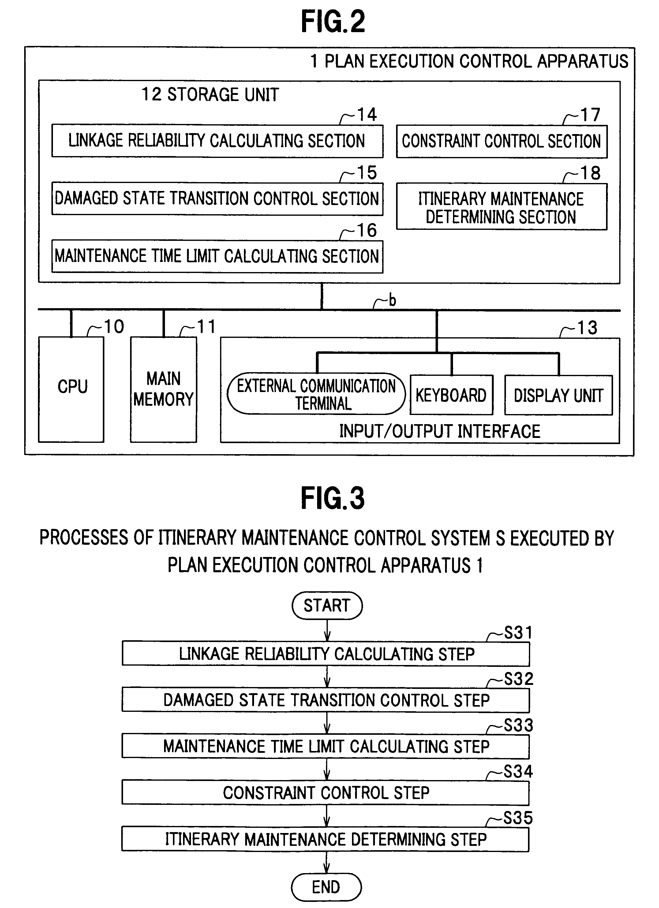
[0017]According to a first aspect of the invention, a plan execution control apparatus for giving an instruction for maintaining installations includes a linkage reliability calculating section for calculating a target reliability indicating a probability that a target installation among one or a plurality of mutually related installations is normally used, a damaged state transition control section that provides a damaged state transition structure of the installation, a maintenance time limit calculating section for calculating a time limit related to a maintenance work to meet a target value of reliability of each key point and section, a constraint control section for recognizing and recording constraints related to traveling of maintenance personnel, a traveling workload, and a workload and an itinerary maintenance determining section for calculating an itinerary schedule indicating an assignment to an object to be maintained among the installations.
[0018]According to a second aspect of the invention, a plan execution control method for giving an instruction for maintaining installations includes a linkage reliability calculating step for calculating a target reliability indicating a probability that a target installation among one or a plurality of mutually related installations is normally used, a damaged state transition control step that provides a damaged state transition structure of the installation, a maintena...

Problems solved by technology

With recent slowing down of growth of power needs, maintenance and control of power installations is drawing increasing attention because it is not expected to improve reliability brought about by an increase of installations per area composed of linked line sections.
However, it is difficult to maintain installations located in a wide area from several tens to several hundreds square kilometers by a limited number of maintenance personnel.
That is, it is difficult to monitor changes of states when the installations to be maintained located in the wide area from several tens to several hundreds square kilometers and it also takes a large amount of time to restore the installations including a traveling time of the maintenance personnel to go to a site where a state change occurs.
However, because the standard for carrying out the maintenance in the temporally planned maintenance is designed to control inspection time intervals of each individual installation independently of the others, there is a problem that this method permits to keep soundness of only each individual installation.
However, the temporally planned maintenance that uniformly plans maintenance has a problem that it is unable to suitably maintain such installations linked with each other as described above.
It is not possible to maintain the installations such as a power network located in a wide area highly reliably and efficiently while keeping a maintenance time required for traveling and others short.
At this time, a maintenance system alternative for the periodic inspection and periodic replacement has not yet been established regarding the electricity distribution installations.
Still more, because a failure of an individual installation is not always directly related to a failure of a system having the installation, there is a difficulty that minimization of failures of individual installations does not always contribute to attainment of good maintenance of the system.

Method used


Image

  • Plan execution control apparatus, plan execution control method, and plan execution control program
  • Plan execution control apparatus, plan execution control method, and plan execution control program
  • Plan execution control apparatus, plan execution control method, and plan execution control program

Examples


Embodiment Construction

[0034]An embodiment of the present invention will be explained below with reference to the drawings.

1>>

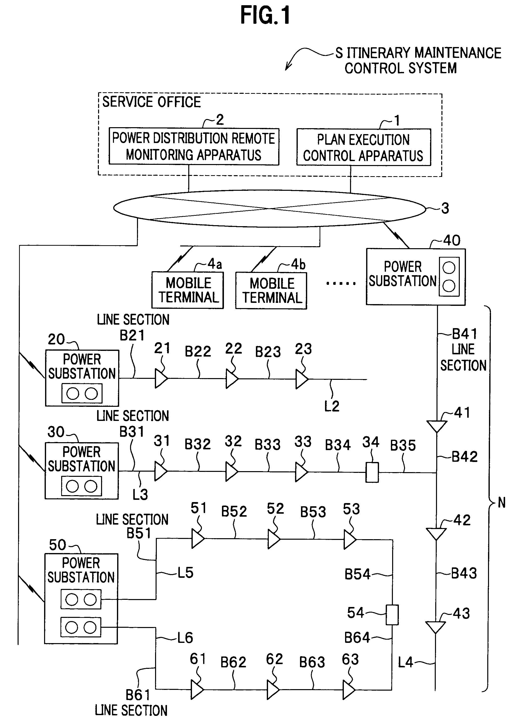
[0035]FIG. 1 is a block diagram showing an exemplary hardware structure of an itinerary maintenance control system S according to an embodiment of the present invention.

[0036]The embodiment of the invention provides the itinerary maintenance control system S (see FIG. 1) of a plan execution control apparatus 1 for drawing up a maintenance work plan of electricity distribution installations.

[0037]FIG. 4 is a data flow chart showing exchanges of processing data of the itinerary maintenance control system of the plan execution control apparatus 1.

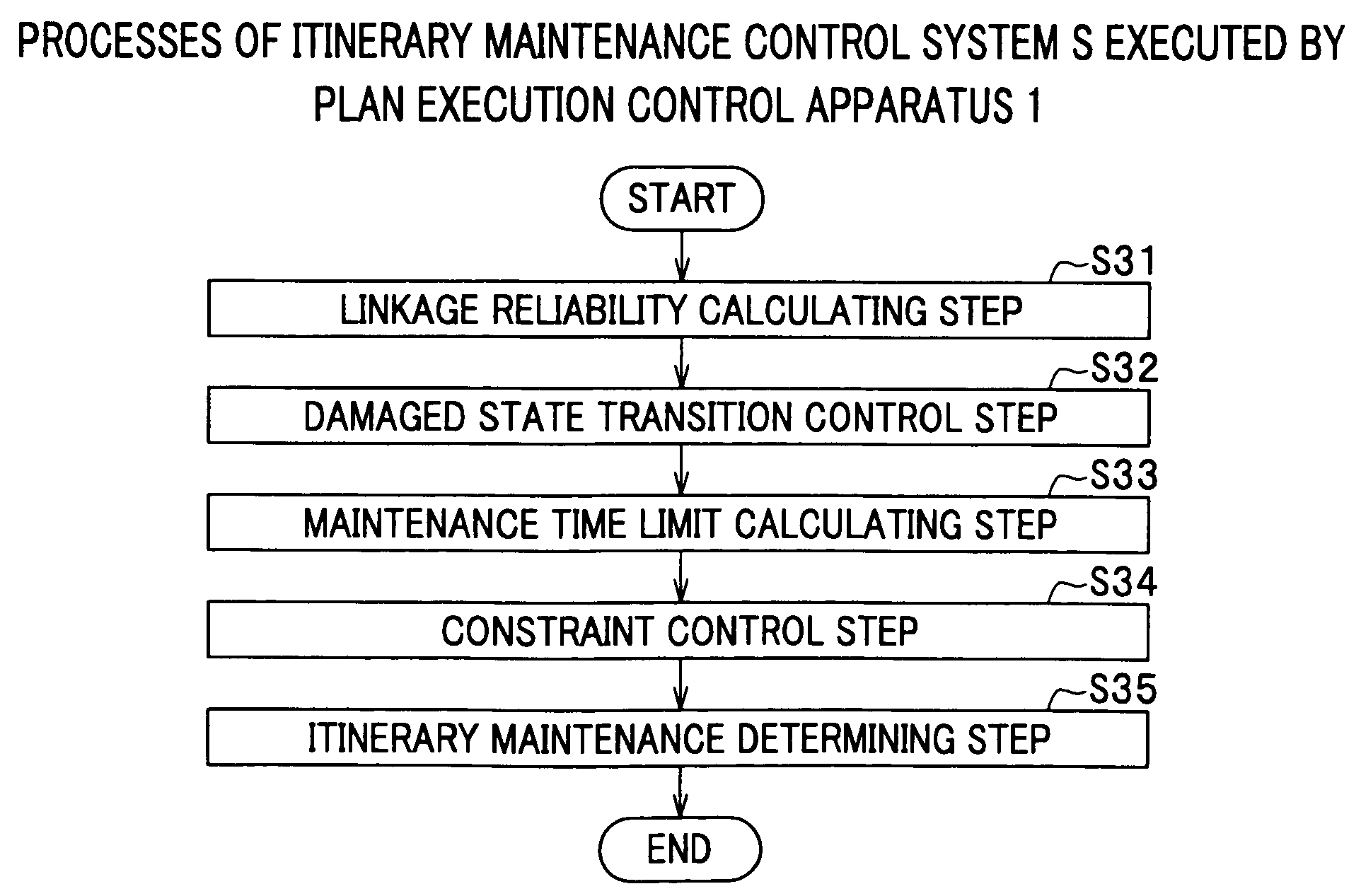
[0038]As shown in FIG. 4, the processes of the plan execution control apparatus 1 shown in FIG. 1 includes a linkage reliability calculating step (Step S31) of calculating a target soundness that is a target value of a probability that line sections B21, B31, B41, B51 and so on of the power distribution installations (see FIG. 1) are not faul...


PUM


Abstract

The invention provides a plan execution control apparatus, a plan execution control method and a plan execution control program capable of giving instructions for sensitively and efficiently maintaining even installations located in a wide range. The plan execution control apparatus includes a linkage reliability calculating section for calculating a target reliability of a single or a plurality of mutually related installations, a damaged state transition control section that provides a damaged state transition structure of the installations, a maintenance time limit calculating section for calculating a time limit related to the maintenance work to meet the target level of reliability of each key point and section, the constraint control section for recognizing and recording the constraints related to traveling of maintenance personnel, the traveling workload and the acceptable workload, and the itinerary maintenance determining section for calculating the itinerary schedule indicating the assignment to the object to be maintained.

Description

CROSS REFERENCE TO RELATED APPLICATIONS[0001]This application claims the foreign priority benefit under Title 35, United States Code, §119 (a)-(d) of Japanese Patent Application No. 2008-129016, filed on May 16, 2008, in the Japan Patent Office, the disclosure of which is herein incorporated by reference in its entirety.BACKGROUND OF THE INVENTION[0002]1. Field of the Invention[0003]The present invention relates to a system for planning and controlling maintenance of installations and more specifically to a plan execution control system, a plan execution control method and a plan execution control program that output instructions for efficiently maintaining broadly spread installations.[0004]2. Description of Related Art[0005]With recent slowing down of growth of power needs, maintenance and control of power installations is drawing increasing attention because it is not expected to improve reliability brought about by an increase of installations per area composed of linked line se...

Claims


Application Information

Patent Timeline
IPC IPC(8): G06Q10/00G06N5/02G06Q50/00G05B19/418G06Q50/10H02J3/00
CPCG06Q10/06G06Q10/0639G06Q10/0631
Inventor WATANABE, TOHRUHORI, HIROYUKI
Owner HITACHI LTD
Learn More