
Electric Torque Converter for a Powertrain and Method of Operating a Vehicle

a technology of electric torque converter and powertrain, applied in hybrid vehicles, gearing, instruments, etc., can solve the problem of limited powertrains with only one motor/generator

Inactive Publication Date: 2009-11-26
GM GLOBAL TECH OPERATIONS LLC
View PDF32 Cites 36 Cited by
  • Summary
  • Abstract
  • Description
  • Claims
  • Application Information

AI Technical Summary

Benefits of technology

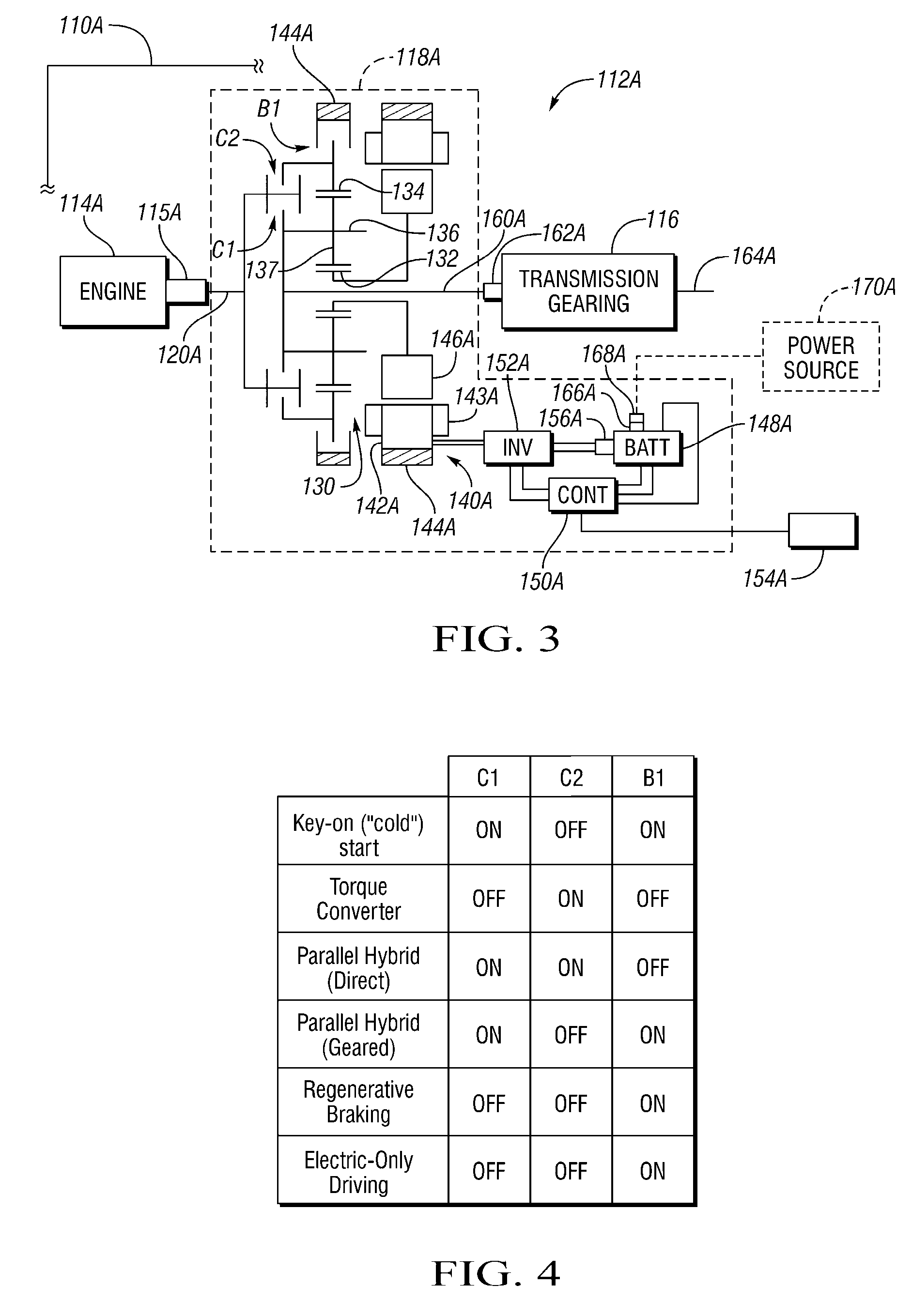
[0005]Preferably, a first clutch is provided to connect the engine with one of the other nodes. If the electric torque converter input member is continuously connected to first node, then engagement of the first clutch locks up the differential gear set such that all elements rotate at the same speed in a hybrid operating mode. However, in some embodiments, the electric torque converter input member is not continuously connected to the first node, in which case a second clutch is provided to selectively engage the torque converter input member and the first node. An engagement schedule for the brake and the first clutch (and the second clutch, if provided in the specific embodiment) allow cold starting of the engine using the motor / generator, a “torque converter” mode in which torque and rotational speed from both the motor / generator and the engine are combined through the differential gear set, as well as parallel hybrid modes in which torque from both the motor / generator and the engine are combined in common rotation. A powertrain having the electric torque converter may have lower assembly and component costs than hybrid electrically variable powertrains offering similar mode capabilities, as they typically require two motor / generators. Other hybrid powertrains with only one motor / generator typically are limited to direct parallel hybrid operation and electric-only modes.

Problems solved by technology

Other hybrid powertrains with only one motor / generator typically are limited to direct parallel hybrid operation and electric-only modes.

Method used


Image

  • Electric Torque Converter for a Powertrain and Method of Operating a Vehicle
  • Electric Torque Converter for a Powertrain and Method of Operating a Vehicle
  • Electric Torque Converter for a Powertrain and Method of Operating a Vehicle

Examples


first embodiment

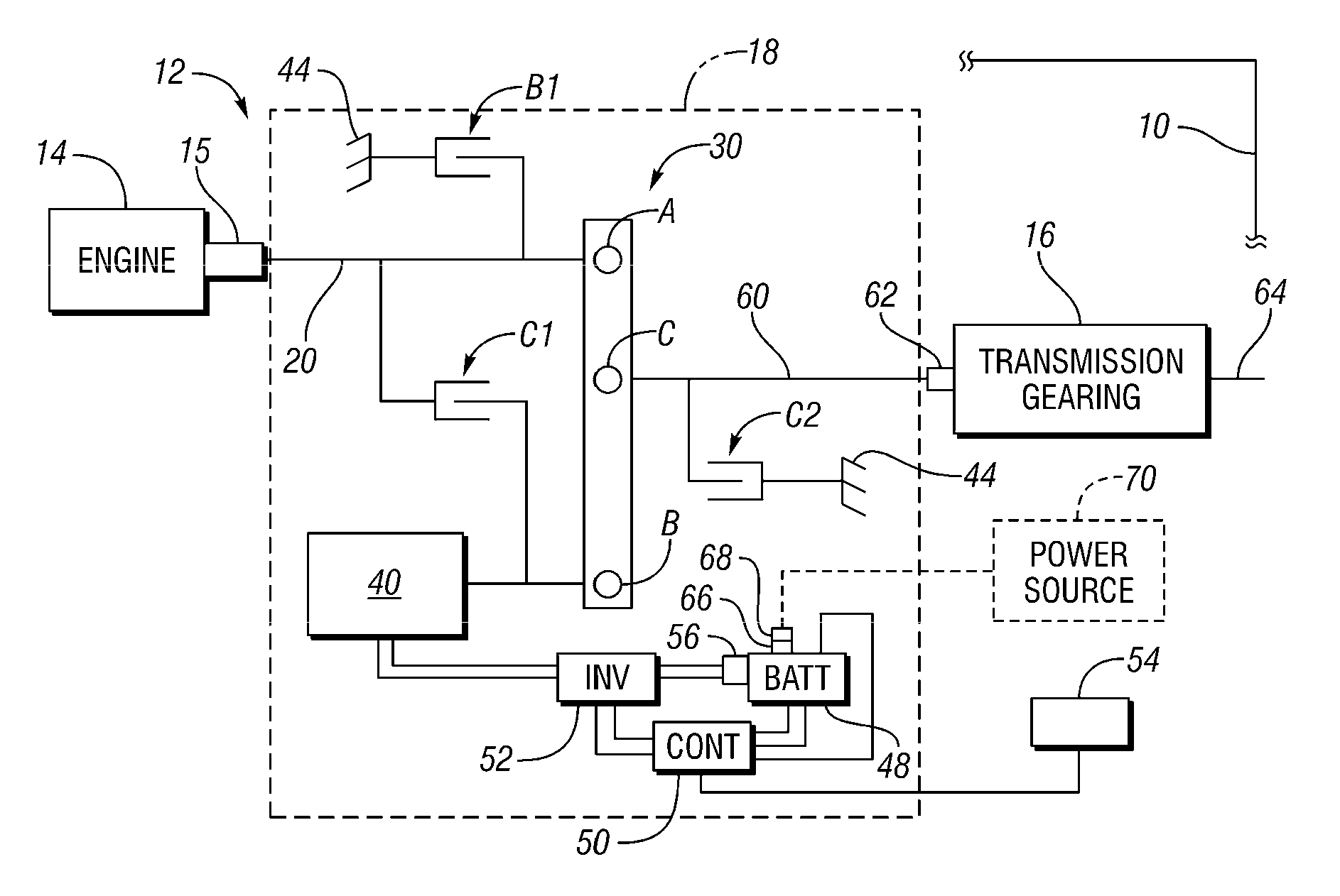
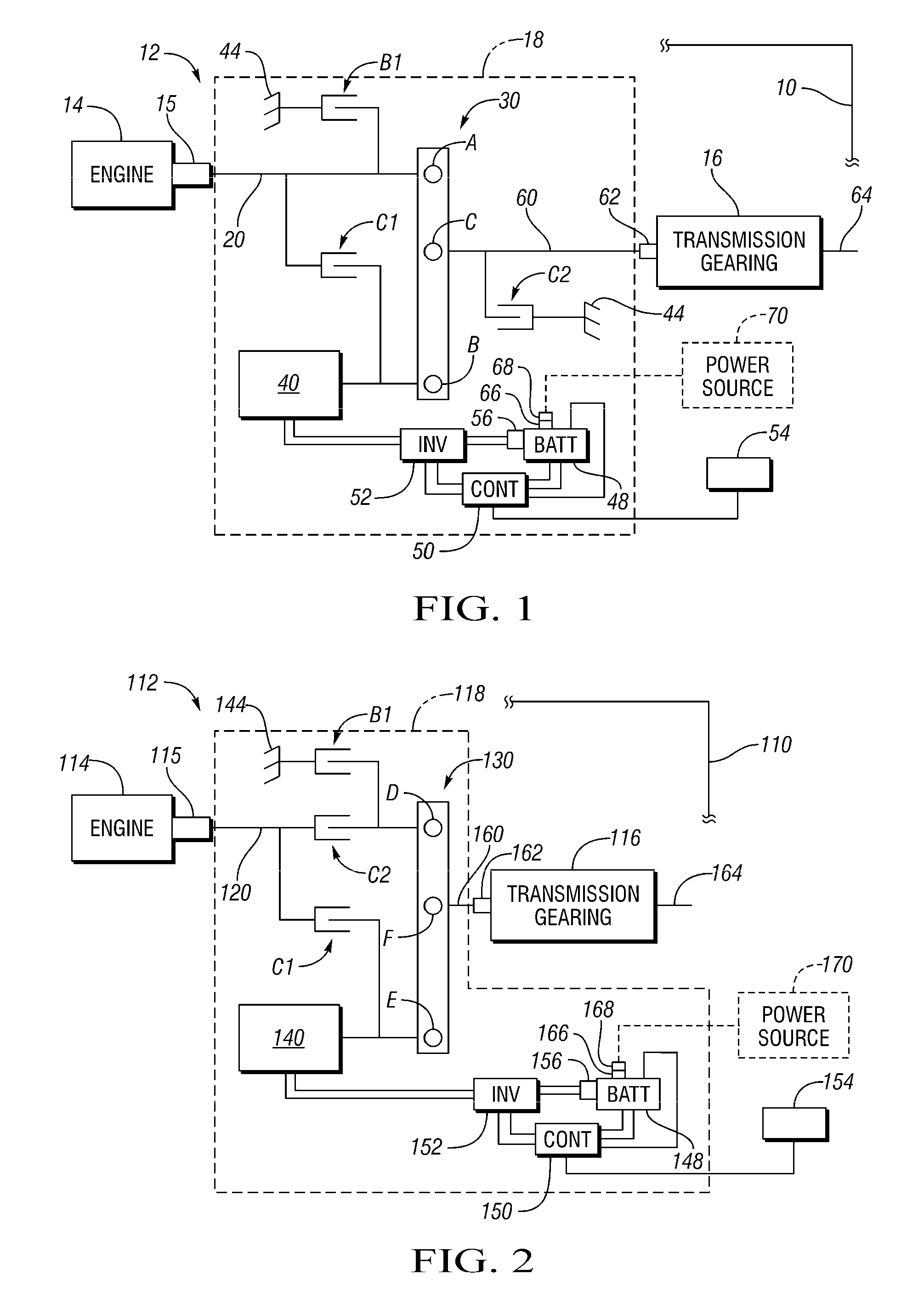
[0013]Referring to the drawings, wherein like reference numbers refer to like components, one representative form of a powertrain utilizing an electric torque converter is depicted in FIG. 1. A vehicle 10 (shown schematically) utilizes a powertrain 12 having an engine 14, a transmission gearing arrangement 16, and an electric torque converter 18 connected therebetween. The electric torque converter 18 may be a replacement for a hydraulic torque converter, as it is located in a similar position between the engine 14 and the transmission gearing arrangement 16. The electric torque converter 18 includes the arrangement of electrical and mechanical components within the dashed lines referred to by the reference number 18. An engine output member 15 directly drives an electric torque converter input member 20, which may be in the nature of a shaft. In the embodiment depicted, the engine 14 may be a diesel engine or other internal combustion engine.

[0014]In addition to the torque converte...

second embodiment

[0030]Another representative form of a powertrain utilizing an electric torque converter is depicted in FIG. 2. A vehicle 110 (shown schematically) utilizes a powertrain 112 having an engine 114, a transmission gearing arrangement 116, and an electric torque converter 118 (including all of the components within the dashed lines 118) connected therebetween. An engine output member 115 directly drives an electric torque converter input member 120, which may be in the nature of a shaft. In the embodiment depicted, the engine 114 may be a diesel engine or other internal combustion engine.

[0031]In addition to the torque converter input member 120, the electric torque converter 118 include a differential gear set 130 represented in lever diagram form having a first node D, a second node E and a third node F. Preferably, the differential gear set 130 is a planetary gear set with a sun gear member represented by node E, a planet carrier member represented by node F, and a ring gear member r...


PUM


Abstract

An electric torque converter has a torque converter input member connected to the first node of a differential gear set representable by a lever diagram having first, second, and third nodes. A motor / generator is connected to the second node. The third node is connected to an input member of a transmission gearing arrangement. A brake is selectively engagable to ground the first node to a stationary member. Engagement of the brake provides a regenerative braking mode and an electric-only driving mode, with the motor / generator connected to the transmission gearing arrangement through the differential gear set. Various clutches may be provided for lock-up or selective connection of the engine, including arrangements which reduce motor / generator torque required for engine starting while in electric-only driving. A method of operating a vehicle maintains the engine speed at an optimum level to the extent possible given battery charge levels and operator commands.

Description

TECHNICAL FIELD[0001]The invention relates to a powertrain having an electric torque converter as well as to a method of operating a vehicle.BACKGROUND OF THE INVENTION[0002]Powertrains having an automatic transmission often utilize a hydraulic torque converter connected between an internal combustion engine and a gearing arrangement with selectable fixed ratios. The torque converter is a fluid coupling that reduces speed and multiplies torque, thus increasing the overall speed ratio of the transmission. The torque converter allows the engine to spin somewhat independently of the transmission, thus partially decoupling the engine from the transmission, and allowing the engine to turn when the car is idling without requiring great braking force on the transmission.[0003]Hybrid electrically variable powertrains include an engine and a transmission that receives power flow from the engine and from one or more motor / generators. Hybrid electrically variable transmissions have a different...

Claims


Application Information

Patent Timeline
Patent Type & Authority Applications(United States)
IPC IPC(8): B60K6/20G06F17/00
CPCB60K6/365Y10T477/24B60K6/547B60L2240/423B60W10/06B60W10/08B60W20/00B60W2510/244B60W2520/10B60W2710/0644B60W2710/083F16H3/725F16H2200/2005Y02T10/6269Y02T10/6286Y02T10/642Y02T90/34Y10T477/26B60K6/383Y02T10/62Y02T10/64Y02T90/40B60W20/13B60W10/18
Inventor KLEMEN, DONALDHOLMES, ALAN G.CONLON, BRENDAN M.HENDRICKSON, JAMES D.BUCKNOR, NORMAN K.SCHMIDT, MICHAEL R.
Owner GM GLOBAL TECH OPERATIONS LLC
Learn More