Power control apparatus for high-frequency dielectric heating and power control method for the same

a technology of power control apparatus and high-frequency dielectric heating, which is applied in the direction of dielectric heating, climate sustainability, sustainable buildings, etc., can solve the problems of producing a high-frequency dielectric heating circuit not affected by the type of magnetron, and the inability to continuously change the heating output, etc., to achieve stable output of magnetron, simple configuration, and suppress instantaneous fluctuation of input current waveform information

Active Publication Date: 2009-11-26
PANASONIC CORP
View PDF7 Cites 21 Cited by
  • Summary
  • Abstract
  • Description
  • Claims
  • Application Information

AI Technical Summary

Benefits of technology

[0059]According to the invention, the input current waveform information of the inverter circuit for rectifying AC power supply voltage and converting into AC of a predetermined frequency is converted into the drive signal of the switching transistor of the inverter circuit to suppress instantaneous fluctuation of the input current waveform information. For example, the input current waveform information is converted into an on / off drive signal of the switching transistor of the inverter circuit according to an on time modulation system for use. Therefore, a control loop is formed for correcting input current by inverting so that the portion where the input current is large becomes small and the portion where the input current is small becomes large. Therefore, if there are variations in the types and the characteristics of magnetrons or if there is ebm (anode-cathode voltage) fluctuation caused by the temperature of the anode of the magnetron and the load in the microwave oven or further if there is power supply voltage fluctuation, input current waveform shaping not affected by them can be obtained according to a simpler configuration and stable output of the magnetron is accomplished according to a simple configuration.
[0060]According to the invention, the input current waveform information of the inverter circuit for rectifying AC power supply voltage and converting into AC of a predetermined frequency is converted into the on / off drive current of the switching transistor of the inverter circuit for use. Thus, a control loop is formed for correcting input current so that the portion where the input current is large becomes small and the portion where the input current is small becomes large, and if there are variations in the types and the characteristics of magnetrons or if there is ebm (anode-cathode voltage) fluctuation caused by the temperature of the anode of the magnetron and the load in the microwave oven or if there is power supply voltage fluctuation, input current waveform shaping not affected by them is made possible according to a very simple configuration.
[0061]Since the input voltage waveform information is also input to the control loop, there are the advantages that the starting time of the magnetron is shortened and that the power factor at the time of low input current is improved.

Problems solved by technology

Thus, if an attempt is made to maintain the heater temperature in an appropriate range, the heating output can be changed only in a slight range and it is impossible to continuously change the heating output; this is a problem.
However, in the control, it turned out that waveform shaping cannot follow up variations or types of characteristics of magnetrons, ebm (anode-cathode voltage) fluctuation caused by the temperature of an anode of a magnetron and the load in a microwave oven, or power supply voltage fluctuation because waveform shaping based on “prospective control system” is executed so that the input current waveform becomes close to a sine wave by performing pulse width modulation using a modulation waveform provided by processing and shaping a commercial power supply waveform for an ON / OFF drive pulse of a switching transistor.
The units in the related arts cannot deal with the problems.
Then, producing a high-frequency dielectric heating circuit not affected by the magnetron type is a problem.
Thus, the nonlinear characteristic of the magnetron also varies largely depending on whether the impedance matching is good or bad and therefore producing a high-frequency dielectric heating circuit not affected by the magnetron type is a problem.
Therefore, if the magnetron temperature is matched with a low temperature, when the magnetron temperature becomes high, the input voltage waveform becomes distorted.
Thus, the nonlinear characteristic of the magnetron also varies largely depending on the magnetron temperature difference and therefore producing a high-frequency dielectric heating circuit not affected by the magnetron type is a problem.

Method used


Image

  • Power control apparatus for high-frequency dielectric heating and power control method for the same
  • Power control apparatus for high-frequency dielectric heating and power control method for the same
  • Power control apparatus for high-frequency dielectric heating and power control method for the same

Examples


fifth embodiment

[0170]In a fifth embodiment of the invention, the characteristic of a mix circuit for mixing input current waveform information of an input current detection section and power control information for controlling so that output of the input current detection section becomes a predetermined value is controlled by providing a difference between the input current increase control time and the decrease control time, as shown in a configuration drawing of the mix circuit relating to the fifth embodiment in FIG. 6.

[0171]In a configuration drawing of FIG. 6 (a), SW1 is turned on / off according to power control information 91 for lowering / raising ON voltage information 92. At the input current increase control time, the SW1 is turned off and the ON voltage information is gradually raised according to a time constant of C*R2 for widening the on width of a switching transistor, as shown in an equivalent circuit of FIG. 6 (b).

[0172]At the input current decrease control time, the SW1 is turned on...

sixth embodiment

[0174]A sixth embodiment of the invention inputs collector voltage control information for controlling the collector voltage of the switching transistor 39 to a predetermined value to the mix circuit 81A, as shown in a configuration drawing of the mix circuit relating to the sixth embodiment in FIG. 7.

[0175]On / off control of SW2 is performed according to collector voltage control information 93 provided by making a comparison between the collector voltage and a reference value, as shown in FIG. 7. If the collector voltage is low, the SW2 is turned off and ON voltage information is gradually raised according to a time constant of C*R2 for widening the on width of the switching transistor. If the collector voltage is high, the SW2 is turned on and the ON voltage information is rapidly lowered according to a time constant of C*{R2*R3 / (R2+R3)} for narrowing the on width of the switching transistor. That is, the circuit configuration of the mix circuit 81A is switched in response to the ...

seventh embodiment

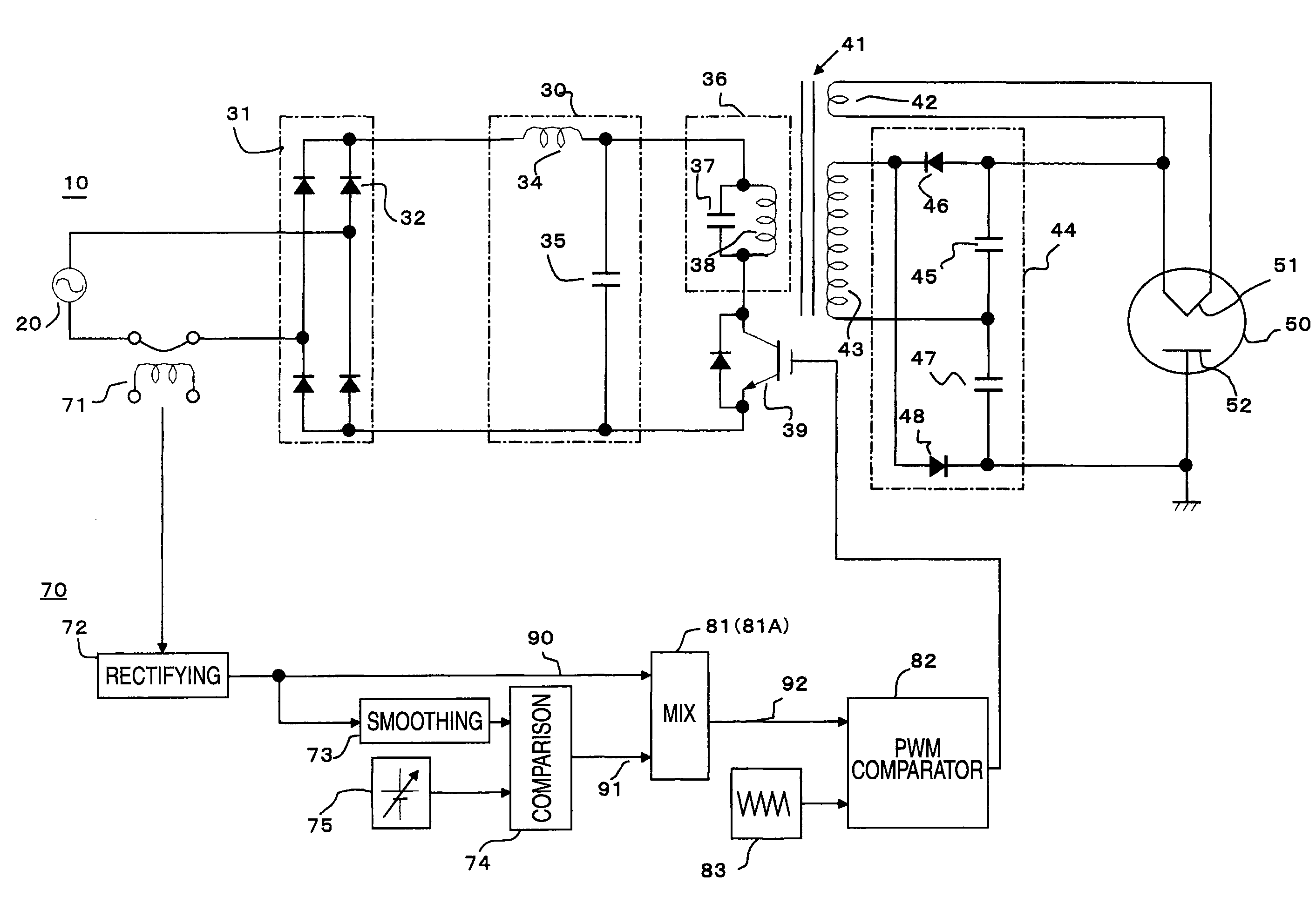
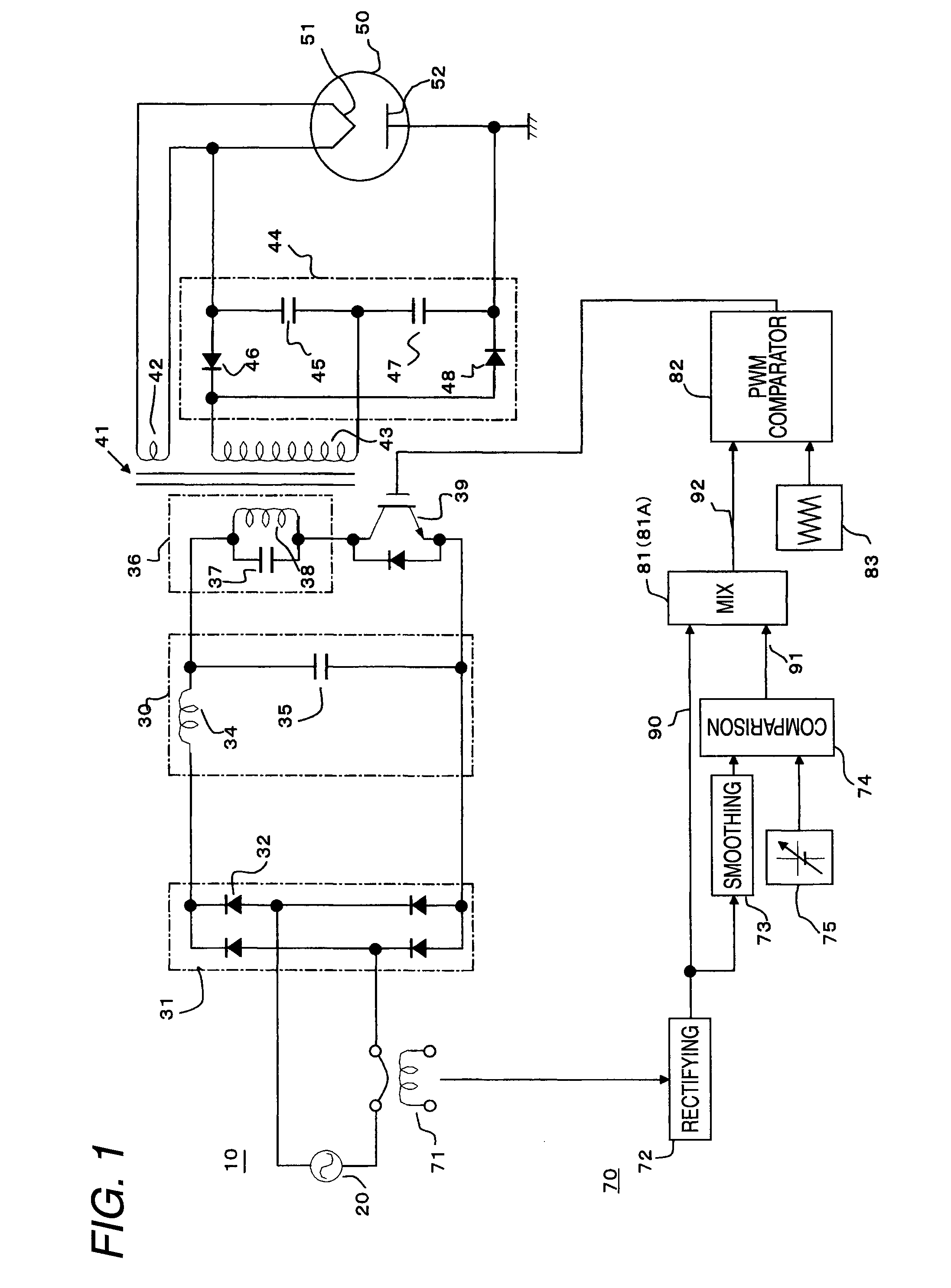
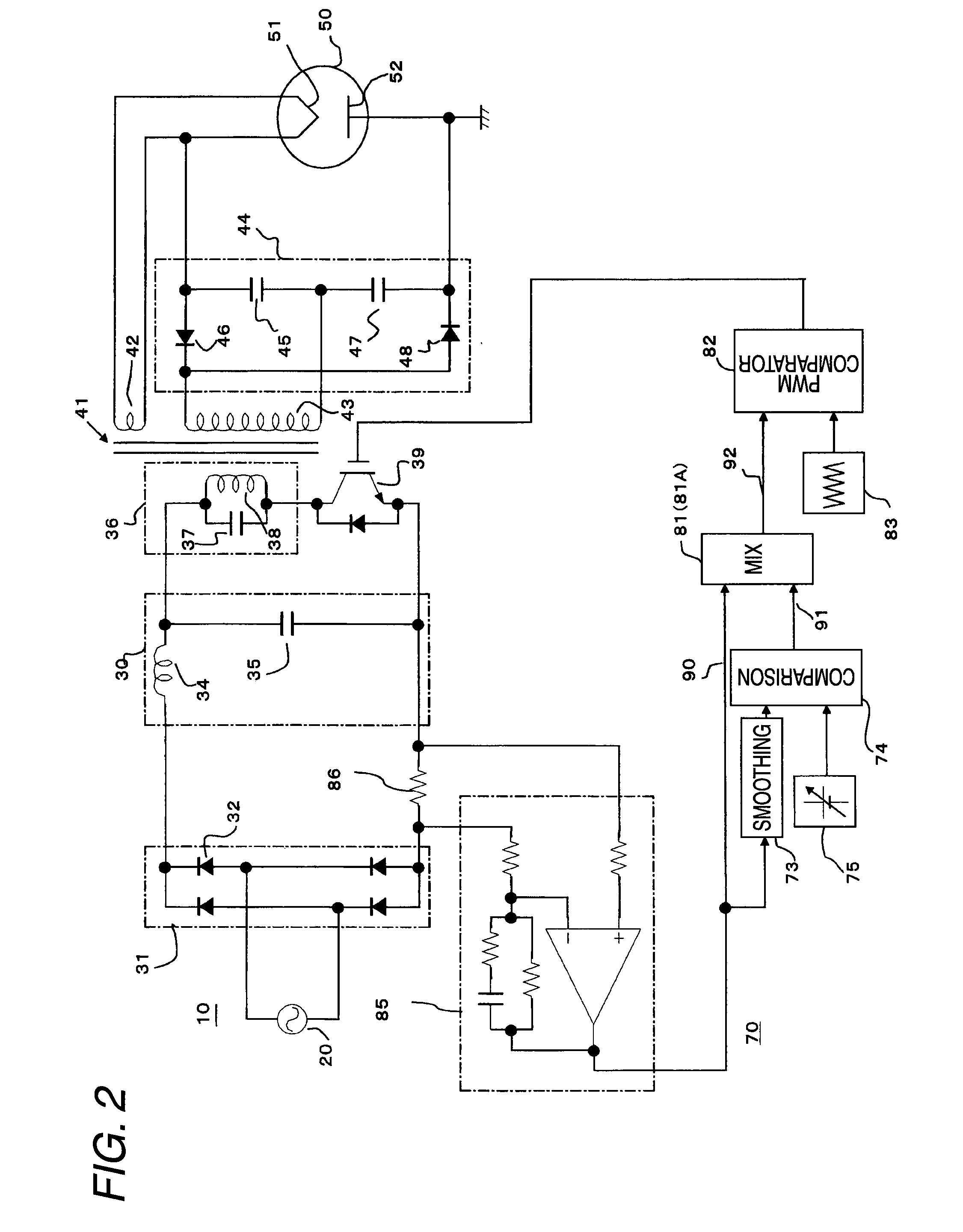
[0177]FIG. 8 is a block diagram to describe a high-frequency heating unit according to a seventh embodiment of the invention. As shown in FIG. 8, in the embodiment, a control circuit 70 also includes an input voltage detection section made up of a pair of diodes 61 for detecting and rectifying voltage of an AC power supply 20 and a shaping circuit 62 for shaping the waveform of the rectified voltage to generate input voltage waveform information 94 in addition to the configuration of the first embodiment. Like that in FIG. 2, a current detection section of a shunt resistor 86 provided between the diode bridge type rectifying circuit 31 and the smoothing circuit 30 and an amplification circuit 85 for amplifying the voltage across the shunt resistor may make up an input current detection section and output thereof may be adopted as input current waveform information 90, as shown in FIG. 9. The shunt resistor 86 detects an input current after rectified in a single direction by the diod...


PUM


Abstract

A power control unit for high-frequency dielectric heating not affected by variations in the types or the characteristics of magnetrons, power supply voltage fluctuation, etc., is provided.The unit has an input current detection section 71, 72 for detecting input current of an inverter circuit 10 for rectifying 31 AC power supply voltage 20, performing high frequency switching, and converting into high frequency power, mixes input current waveform information 90 of the input current detection section and power control information 91 for controlling so that output of the input current detection section becomes a predetermined value in a mix circuit 81, outputs ON voltage information 92, makes a comparison between the ON voltage information and a sawtooth wave from a sawtooth wave generation circuit 83 in a PWM comparator 82, performs pulse width modulation, and outputs a drive signal for controlling turning on / off of a switching transistor 39 of an inverter circuit.

Description

TECHNICAL FIELD[0001]This invention relates to a power control for high-frequency dielectric heating using a magnetron such as a microwave oven and in particular to high-frequency dielectric heating not affected by variations or types of characteristics of magnetrons or the difference in the temperatures, etc., of anodes of magnetrons.BACKGROUND ART[0002]A known high-frequency heating unit in a related art adjusts power supplied to a magnetron according to the width of the output pulse from an inverter control circuit. As the output voltage of signal superposition means becomes higher, the output pulse width of the inverter control circuit widens and the power supplied to the magnetron increases. This configuration makes it possible to change the output voltage of the signal superposition means for continuously changing the heating output of the magnetron.[0003]Since a heater also serves as a cathode of the magnetron, a transformer for supplying power to the magnetron also supplies ...

Claims


Application Information

Patent Timeline
Patent Type & Authority Applications(United States)
IPC IPC(8): H05B6/50
CPCH05B6/685Y02B40/00
Inventor SUENAGA, HARUOYASUI, KENJISAKAI, SHINICHISHIROKAWA, NOBUOMORIYA, HIDEAKIKINOSHITA, MANABU
Owner PANASONIC CORP
Why Eureka
Try Eureka