Spark plug

a technology of spark plugs and spark plugs, applied in spark plugs, basic electric elements, electrical appliances, etc., can solve the problems of ground electrodes obstructing the flow of mixture gas into spark discharge gaps, and feared variations in ignitability, etc., to achieve stably, increase the cost, and increase the cost

Active Publication Date: 2009-11-26
NGK SPARK PLUG CO LTD
View PDF13 Cites 18 Cited by
  • Summary
  • Abstract
  • Description
  • Claims
  • Application Information

AI Technical Summary

Benefits of technology

[0008]However, for the reason that the ground electrode is to be joined to the front end surface of the metallic shell, if the cross section of the ground electrode is circular-shaped, its sectional area inevitably becomes smaller as compared with the case where the cross section is rectangular-shaped. As a result, there is a fear of a so-called heat-drawing (heat radiation ability) becoming worse, and the electrode temperature rising easily at high-speed driving and the like such that the rate of exhaustion of the ground electrode becomes larger and its durability is lowered.

Problems solved by technology

In the meantime, in case in an installed state of the spark plug, the mixture gas has such a positional relationship of lashing against a back face of the ground electrode, there is a fear of the ground electrode obstructing flow of a mixture gas into a spark discharge gap.
As a result, there is a fear of variations in the ignitability being caused.

Method used


Image

  • Spark plug
  • Spark plug
  • Spark plug

Examples


first embodiment

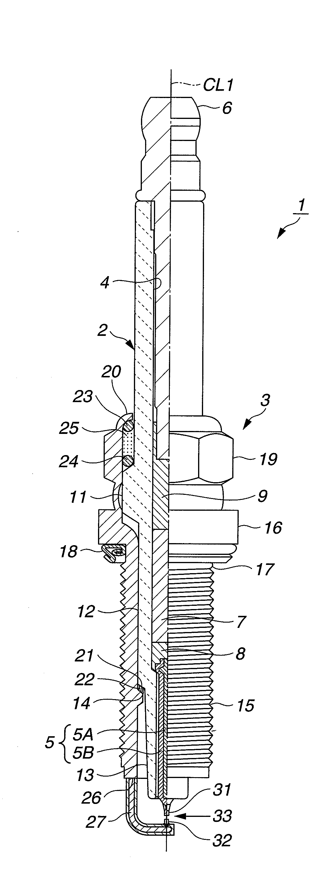
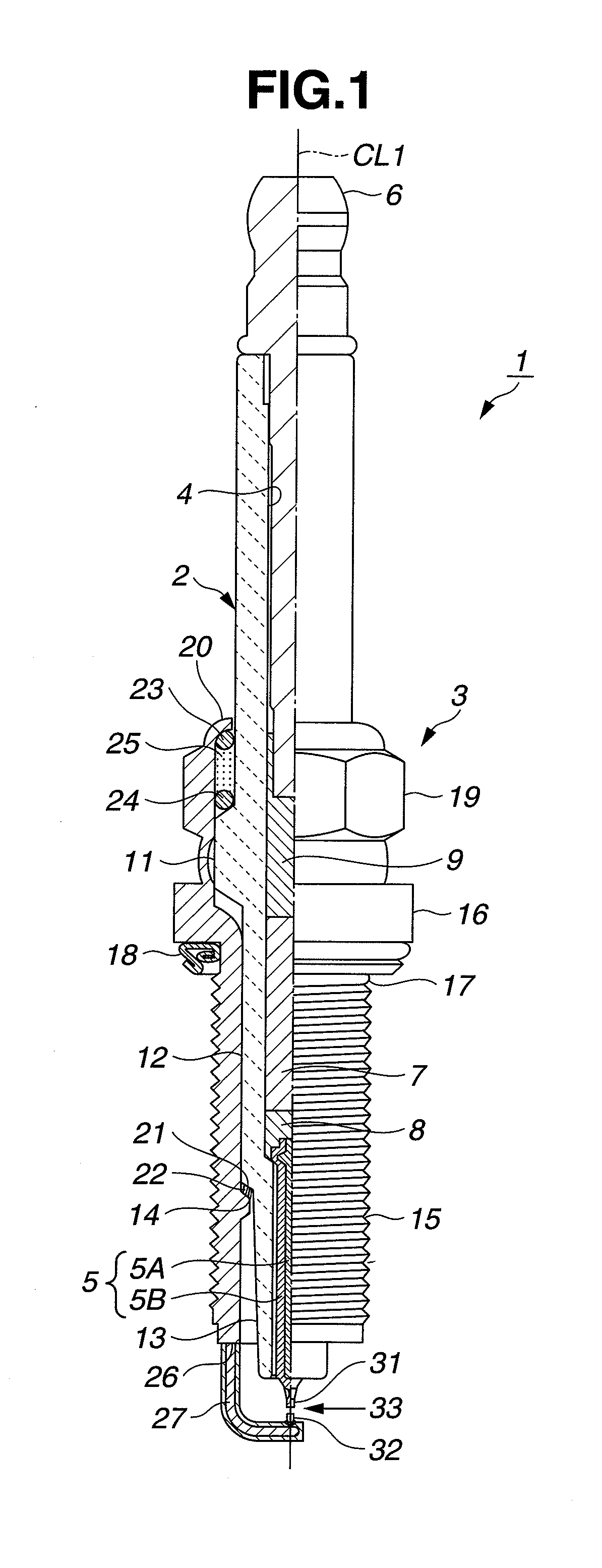
[0059]Hereinafter, the first embodiment will be described with reference to drawings. FIG. 1 is a partially cutaway elevational view showing a spark plug 1. In the meantime, description will be made by regarding, in FIG. 1, an axial CL1 direction of the spark plug 1 as a vertical direction in the drawing, the lower side as the front end side of the spark plug 1 and the upper side as the rear end side.

[0060]The spark plug 1 is constituted by an insulator 2 having a long shape, a tubular metallic shell 3 holding the insulator and so on.

[0061]The insulator 2 is formed with an axial hole 4 extending therethrough along an axis CL1. Into the front end side of the axial hole 4 is inserted and fixed thereat a center electrode 5. Further, into the rear end side of the axial hole 4 is inserted and fixed thereat a terminal electrode 6. Between the center electrode 5 and the terminal electrode 6 within the axial hole 4 is disposed a resistor 7, and the resistor 7 is electrically connected to th...

second embodiment

[0093]Then, the second embodiment will be described with reference to FIGS. 8 to 10. However, in the second embodiment, the same reference characters are used for the same or like parts as the first embodiment while their duplicate description being omitted, and the different point from the first embodiment will be mainly described.

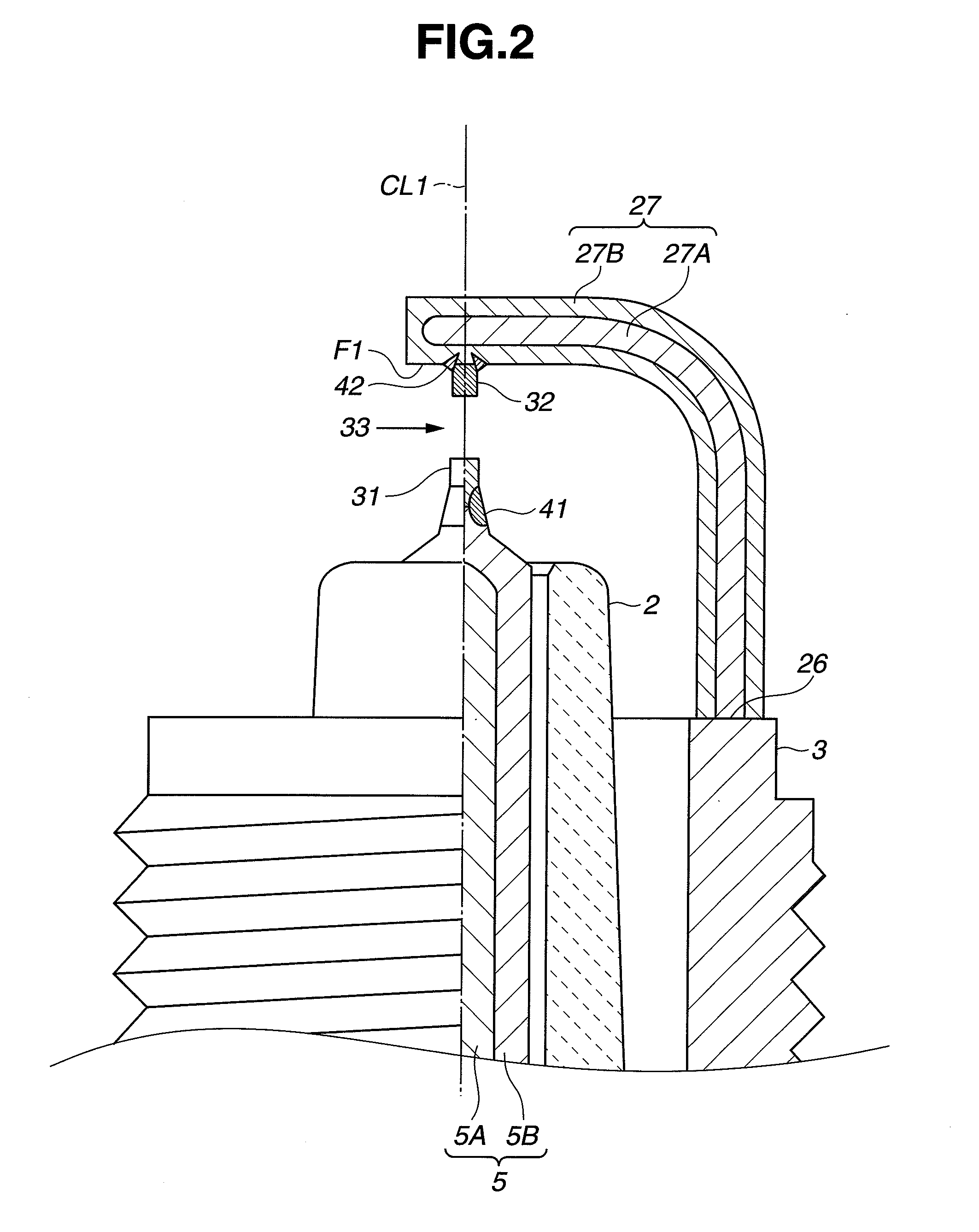
[0094]In the first embodiment, in the cross section of the ground electrode 27 as viewed from the front end surface side of the ground electrode 27 along the axis CL1, the second noble metal tip 32 side shape of the inner layer 27A is substantially flat. In contrast to this, this embodiment features that, as shown in FIG. 8, the second noble metal tip 32 side shape of the inner layer 27 is recessed.

[0095]The ground electrode 27 is obtained, for example, in the following manner. Namely, as shown in FIG. 9A, a core member 51 made of a metallic material constituting the inner layer 27A and a bottomed tubular body 52 made of a metallic material constituting t...

third embodiment

[0109]Then, the third embodiment will be described with reference to FIG. 12. However, in the third embodiment, the same reference characters are used for the same or like parts as the first embodiment while their duplicate description being omitted, and the different point from the first embodiment will be mainly described.

[0110]In the first embodiment, in the cross section of the ground electrode 27 as viewed from the front end surface side of the ground electrode 27 along the axis CL1, only the second noble metal tip 32 side is provided with the flat surface F1. In contrast to this, in this embodiment, the back surface on the side opposite to the flat surface F1 is also provided with a flat surface F2. Further, this embodiment features that the inner layer 27A has a pair of flat surfaces corresponding to not only the flat surface F1 but also the flat surface F2.

[0111]In the above-described cross section, the portions of the ground electrode 27 except for the flat surfaces F1 and ...


PUM

PropertyMeasurementUnit
heightaaaaaaaaaa
distanceaaaaaaaaaa
depthaaaaaaaaaa

Abstract

A spark plug comprising a center electrode, a first noble metal tip joined to the center electrode, an insulator, a metallic shell, a ground electrode joined to the metallic shell and including an outer layer and an inner layer, and a second noble metal tip joined to the ground electrode by way of a melted portion, wherein in a cross section of the ground electrode, the protrusion height A of the second noble metal tip is 0.4 mm or more, the ground electrode includes a substantially flat joining surface to which the second noble metal tip is joined and an outwardly curved surface, the inner layer has at the joining surface side a substantially flat surface or recessed surface, and the minimum distance F between the melted portion and the inner layer is 0.1 mm or more.

Description

TECHNICAL FIELD[0001]The present invention relates to a spark plug for use with an internal combustion engine.BACKGROUND TECHNIQUE[0002]A spark plug for an internal combustion engine such as an automotive engine is provided with, for example, a center electrode, an insulator provided at the outside of the center electrode, a tubular metallic shell provided at the outside of the insulator and a ground electrode with a base end portion joined to a front end surface of the above-described metallic shell. The ground electrode has a substantially rectangular cross section and is disposed so that its front end portion inner surface faces a front end portion of the above-described center electrode, whereby a spark discharge gap is formed between the front end portion of the center electrode and the front end portion of the ground electrode.[0003]The metallic shell is formed at an outer circumferential surface with an unshown thread portion. The spark plug is threadedly attached to a spark ...

Claims


Application Information

Patent Timeline
Patent Type & Authority Applications(United States)
IPC IPC(8): H01T13/20
CPCC22C5/04H01T13/39H01T13/32H01T13/20
Inventor NUNOME, KENJISATO, YOSHIKUNI
Owner NGK SPARK PLUG CO LTD
Why Eureka
Try Eureka