
Image processing apparatus

a technology of image processing and image input, which is applied in the field of image processing apparatus and image input method, can solve the problems of not only bulky sensor or system, but also impose various restrictions, and the basic performance of the imaging device would decline too much to maintain the minimum required level in terms of sensitivity or diffraction,

Active Publication Date: 2009-11-26
PANASONIC CORP
View PDF7 Cites 73 Cited by
  • Summary
  • Abstract
  • Description
  • Claims
  • Application Information

AI Technical Summary

Benefits of technology

[0029]An image processing apparatus according to the present invention can obtain a color image and polarization information at the same time by eliminating interference between the color separation property and the polarization separation property and by getting the color intensity and polarization monitored simultaneously on an image capturing system.

Problems solved by technology

However, if the size of an optical system or an image capture element were reduced significantly, then the basic performance of the imaging device would decline too much to maintain the minimum required level in terms of sensitivity or diffraction limit of lens.
However, such a sensor or system is not just bulky but also imposes various restrictions.
Besides, such a sensor or system cannot be used unless the object is a solid and bright diffusive object.
Under such a restriction, the sensor or system cannot be used to shoot an object located at a distance outdoors or take a close up photo of a person with his or her hair and clothes shot as beautifully as possible.
However, this camera cannot obtain a single piece of polarization information until several frames are shot with the polarization main axes of the polarizer changed by applying a voltage to the liquid crystal layer.
In other words, these two images cannot be obtained at the same time.
However, since a difference between two different polarization pixels is simply calculated, information about the degree of partial polarization of the object cannot be obtained perfectly.

Method used


Image

  • Image processing apparatus
  • Image processing apparatus
  • Image processing apparatus

Examples


embodiment 1

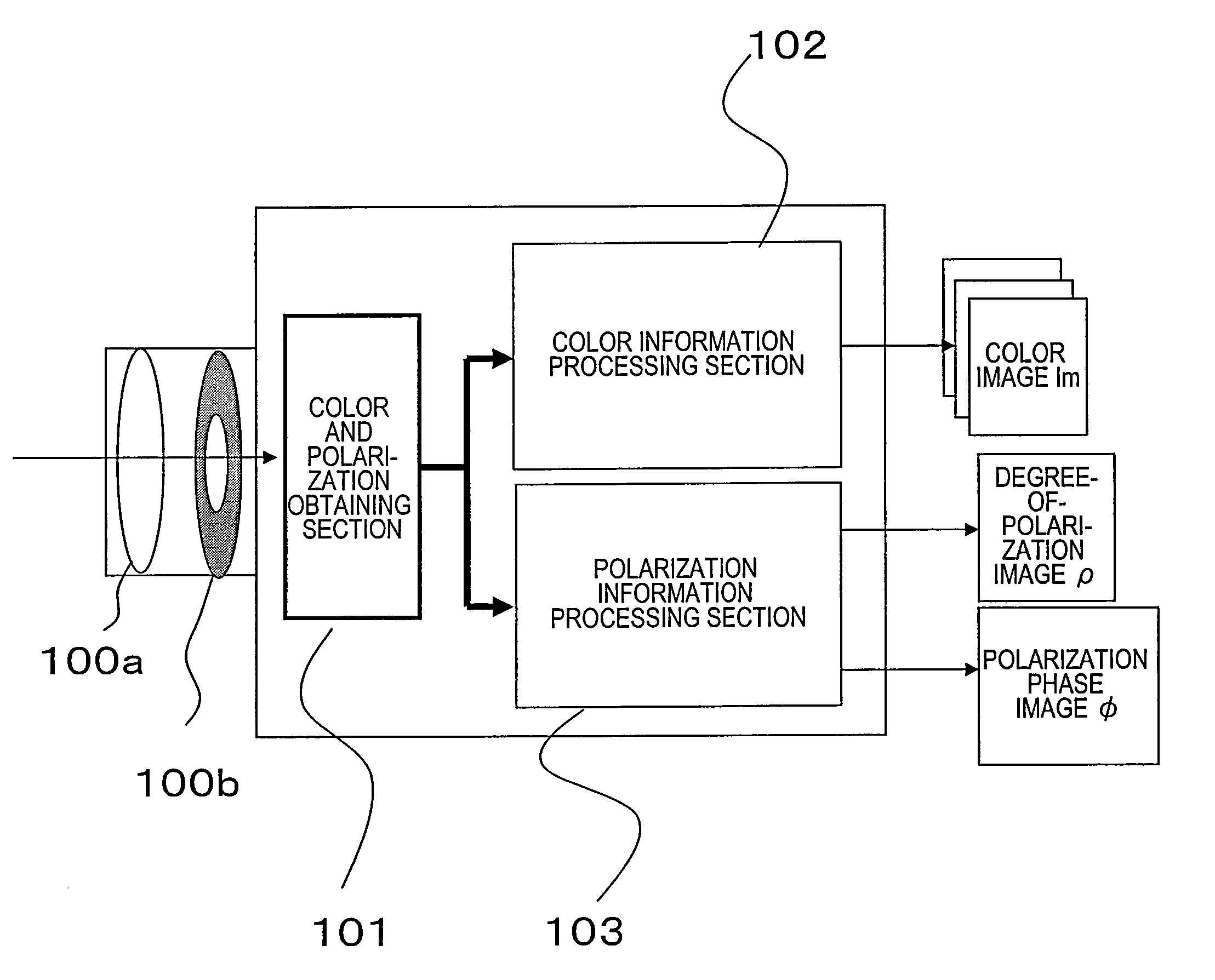
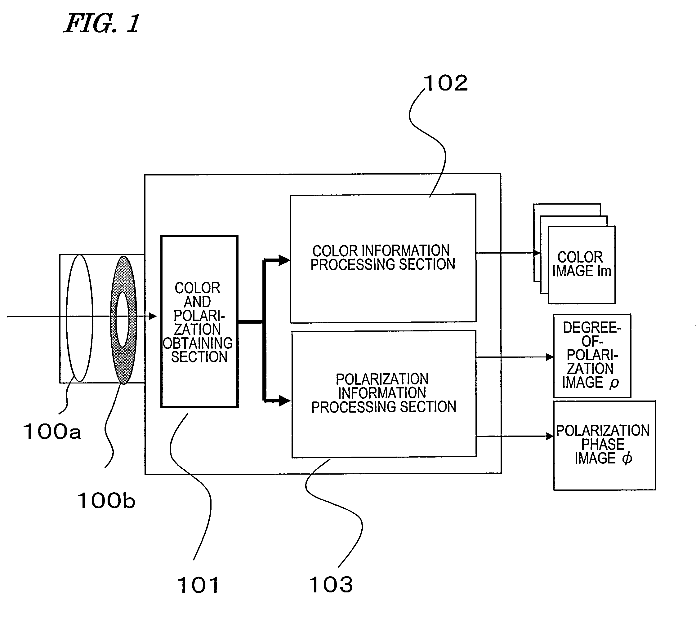
[0063]FIG. 1 is a block diagram illustrating a basic configuration that applies to every preferred embodiment of the present invention to be described herein. The apparatus of this preferred embodiment obtains not only color image information from an object in real time but also polarized image information at the same time, and outputs those pieces of information as two different types of polarized images (i.e., a degree-of-polarization image ρ and a polarization phase image Φ). After having passed through a lens 100a and a diaphragm 100b, the incident light enters a color and polarization obtaining section 101. From this incident light, the color and polarization obtaining section 101 can obtain both color moving picture information and polarized image information in real time. The color and polarization obtaining section 101 of this preferred embodiment can obtain information about colors (which will be referred to herein as “color information”) and information about polarization ...

embodiment 2

[0109]Hereinafter, a second preferred embodiment of an image processing apparatus according to the present invention will be described.

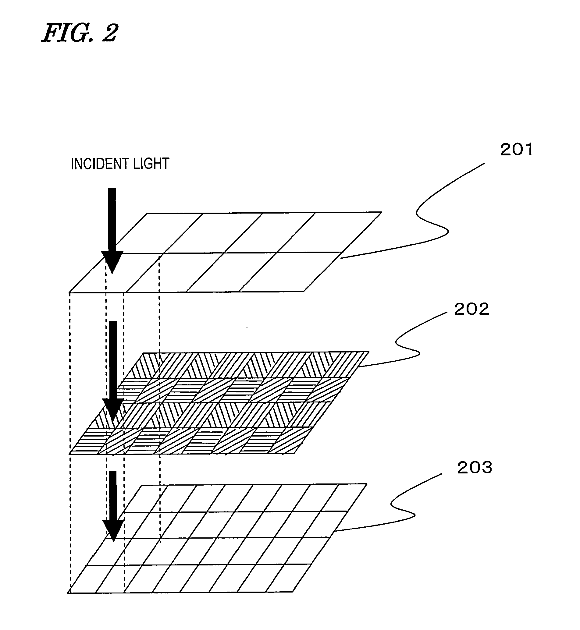
[0110]In the first preferred embodiment described above, a single plate color image capture system is used, and therefore, the resolution achieved is lower than the original resolution of the image capture element. Such a decrease in resolution is caused by the use of the color mosaic filter that separates the color according to the point of incidence of the incoming light. To overcome such a problem, according to this preferred embodiment, the color mosaic filter is replaced with a color separator that separates the light that has been incident on the same area into multiple different colors according to the wavelength range, thereby increasing the resolution compared to the first preferred embodiment described above.

[0111]The basic configuration of this preferred embodiment is also just as shown in the block diagram of FIG. 1. Thus, in the followin...

embodiment 3

[0150]Hereinafter, a third preferred embodiment of an image processing apparatus according to the present invention will be described.

[0151]In the second preferred embodiment described above, patterned polarizers are used, and therefore, the R and B resolutions, in particular, become lower than the original resolutions of the image capture elements. According to this preferred embodiment, such a decrease in R and B resolution can be avoided.

[0152]The basic configuration of this preferred embodiment is also just as shown in the block diagram of FIG. 1. Thus, in the following description of the third preferred embodiment, FIG. 1 will be referred to again when necessary. The image processing apparatus of this preferred embodiment also obtains not only color image information from an object in real time but also polarized image information at the same time, and outputs those pieces of information as two different types of polarized images (i.e., a degree-of-polarization image and a pola...


PUM


Abstract

An image processing apparatus according to the present invention includes: a color and polarization obtaining section 101 including a single-chip color image capture element with a color mosaic filter and a patterned polarizer in which a number of polarizer units, of which the polarization transmission planes define mutually different angles, are arranged adjacent to each other within each single color pixel; a color information processing section 102 for getting average color intensity information by averaging the intensities of the light rays that have been transmitted through the polarizer units within each said single color pixel; and a polarization information processing section 103 for approximating, as a sinusoidal function, a relation between the intensity of light rays that have been transmitted through the polarizer units within each said single color pixel and the angles of the polarization transmission planes of the polarizer units.

Description

TECHNICAL FIELD[0001]The present invention relates to an image processing apparatus and image input method that allow the user to obtain both color information and polarization information alike.BACKGROUND ART[0002]Recently, digital movie cameras have advanced so dramatically that it is expected that cellphones with a camera would achieve as high definition as an HDTV in the near future. However, if the size of an optical system or an image capture element were reduced significantly, then the basic performance of the imaging device would decline too much to maintain the minimum required level in terms of sensitivity or diffraction limit of lens. For that reason, such a high-resolution trend should hit a plateau sooner or later. Even so, however, the image quality can still be improved by compensating for the lack of image information of the object by computer graphics type processing. Nevertheless, for that purpose, pieces of physical information, including information about the thr...

Claims


Application Information

Patent Timeline
IPC IPC(8): H04N5/228G06K9/00H04N9/07H04N9/09
CPCH04N2209/045H04N9/045G01J2003/2806G01J3/0224G01J3/2803G01J3/0205G01J2003/282G01J2003/2826G01J4/04H04N23/84H04N25/134
Inventor KANAMORI, KATSUHIROSATOOKAYAMA, HIROAKI
Owner PANASONIC CORP
Learn More