Reflective liquid crystal display device and reflective liquid crystal projector

Inactive Publication Date: 2009-11-26
FUJIFILM CORP
View PDF4 Cites 7 Cited by
  • Summary
  • Abstract
  • Description
  • Claims
  • Application Information

AI Technical Summary

Benefits of technology

[0022]According to the present invention, the biaxial birefringent medium compensates the phase difference due to the pre-tilt of the liquid crystal molecules in the VAN-LCD as well as the phase difference of the incident light on the l

Problems solved by technology

However, while it provides good contrast when viewed from the front, the VAN-LCD, similar to the other operation modes, hardly keeps good display performance when viewed from an oblique angle, and results in lowering the contrast or causing tone reversal to reverse the brightness of neutral colors.
These drawbacks are due partly to the obliquely incident light on the liquid crystal layer.
If the liquid crystal layer is driven as a densely-arranged pixel array using a micro-electrode structure, a lateral electric field generated when a voltage is applied to the pixels next to the voltage-off pixels produces reverse tilt domains where the liquid crystal molecules for the voltage-off pixels are aligned opposite to an intended direction, and causes poor alignment of the liquid crystal molecules.
However, the C-plate is not able to compensate the phase difference caused by the birefringence due to the pre-tilt of the liquid crystal molecules.
When the C-plate and

Method used


Image

  • Reflective liquid crystal display device and reflective liquid crystal projector
  • Reflective liquid crystal display device and reflective liquid crystal projector
  • Reflective liquid crystal display device and reflective liquid crystal projector

Examples


Example

[0098]Next, with reference to Example 1, the operation of the retardation compensation element 56 is explained. Hereafter, the phase difference is substituted for retardation, the equivalent word, because the phase difference depends on the wavelength and other properties of the light passing through the liquid crystal display device and the retardation compensation element. The retardation, dΔn, is expressed by an equation of dΔn=d·(nx−ny), wherein d represents the physical thickness of the retardation compensation element, nx represents the largest principal refractive index on the element's surface, and ny represents the smallest principal refractive index on the element's surface. Additionally, retardation Rth in the thickness direction of the liquid crystal layer and the C-plate is expressed by an equation of Rth=d·{nz−(nx+ny) / 2}.

Example 1

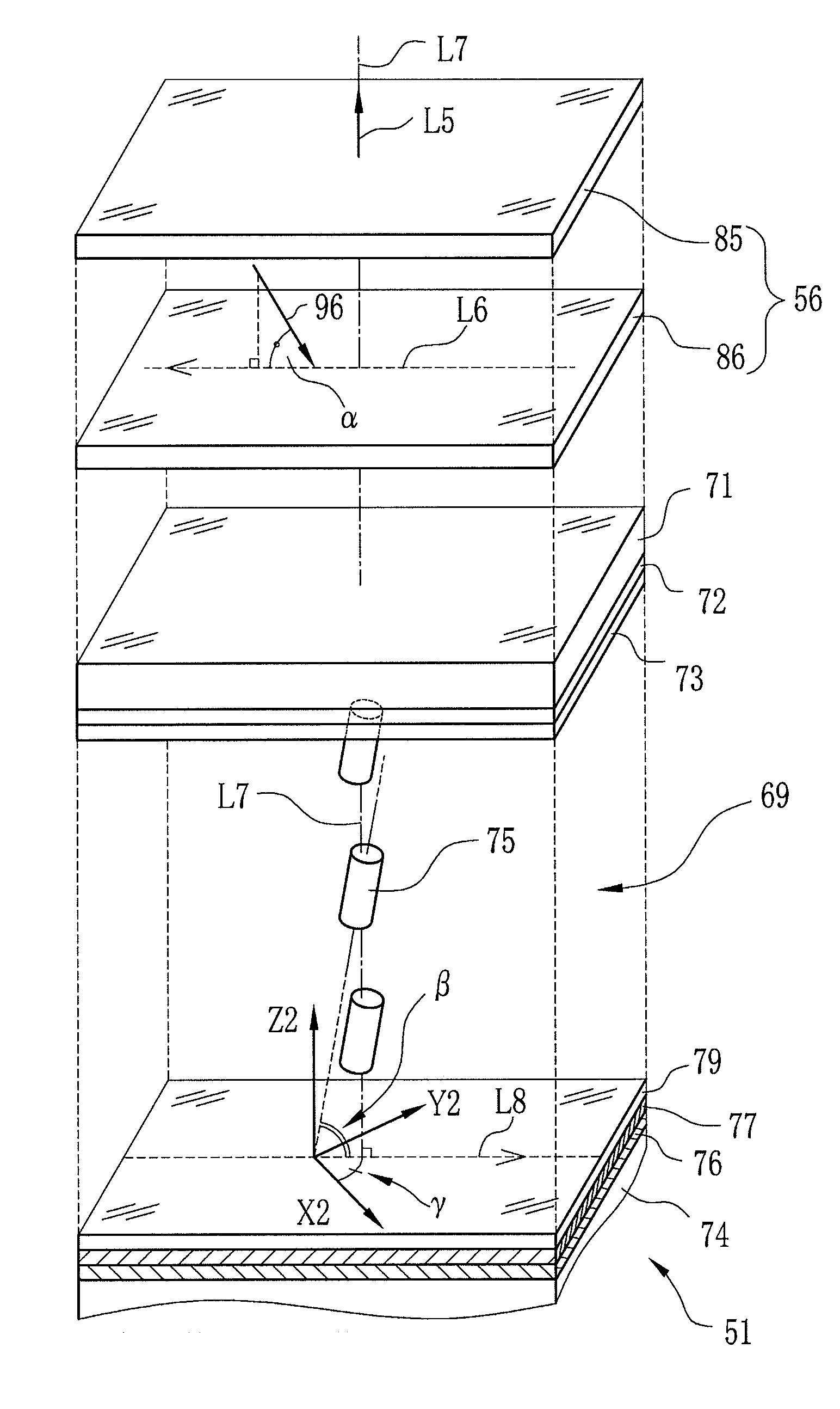
[0099]A liquid crystal display device was prepared to have retardation Rth (in the thickness direction of the liquid crystal layer) of +200 n...


PUM


Abstract

A retardation compensation element (56) is composed of a C-plate (85) and an O-plate (86). The O-plate (86) is a biaxial birefringent medium made of an obliquely deposited organic material. A fast axis (L6) of the O-plate (86) is parallel to the orthographic projection of a deposition direction (96) onto the surface of the O-plate (86). Between a liquid crystal display device (51) and a polarization beam splitter (48), the O-plate (86) is arranged such that the fast axis (L6) and a tilt direction (L8) of liquid crystal molecules (75) are parallel to each other, and that the deposition direction (96) and the tilt direction (L8) face the opposite direction with respect to a Z2 axis. The C-plate (86) is disposed together with the O-plate (85) between the liquid crystal display device (51) and the polarization beam splitter (48).

Description

TECHNICAL FIELD[0001]The present invention relates to a reflective liquid crystal display device and a reflective liquid crystal projector, and more particularly to the reflective liquid crystal display device and the reflective liquid crystal projector having a vertically alignment nematic (VAN) liquid crystals.BACKGROUND ART[0002]A liquid crystal display device (hereinafter, LCD) can be found in a variety of electronic hardware, such as a display of calculators, electronic dictionaries, televisions and digital cameras, a monitor of car navigation system, cellular phones and computers, and a display panel of projectors.[0003]According to the operation modes of a liquid crystal layer, the LCD can be classified into several types, such as TN (Twisted Nematic) LCD, VAN (Vertical Alignment Nematic) LCD, IPS (In-Plane Switching) LCD and OCB (Optically Compensatory Bend) LCD. Based on the purpose of an electronic hardware and the required function, one of these operation modes is selecte...

Claims


Application Information

Patent Timeline
IPC IPC(8): G02F1/13363
CPCG02B27/1026G02B27/145G02B27/149G02F1/133634G02F2413/12G02F2001/13355G02F2413/10G02F2413/11G02F1/1393G02F1/13355
Inventor NAKAGAWA, KENICHIHASHIZUME, TAROTAKAHASHI, HIROKI
Owner FUJIFILM CORP
Why Eureka
Try Eureka