

Endoscope objective lens with large entrance pupil diameter and high numerical aperture
a technology of objective lens and pupil diameter, which is applied in the field of endoscope objective lens with, can solve the problems of not optimizing fluorescence, signal strength is substantially weaker, and the collection efficiency of the objective is very weak
- Summary
- Abstract
- Description
- Claims
- Application Information
AI Technical Summary
Benefits of technology
Problems solved by technology
Method used
Image

Examples
example 1
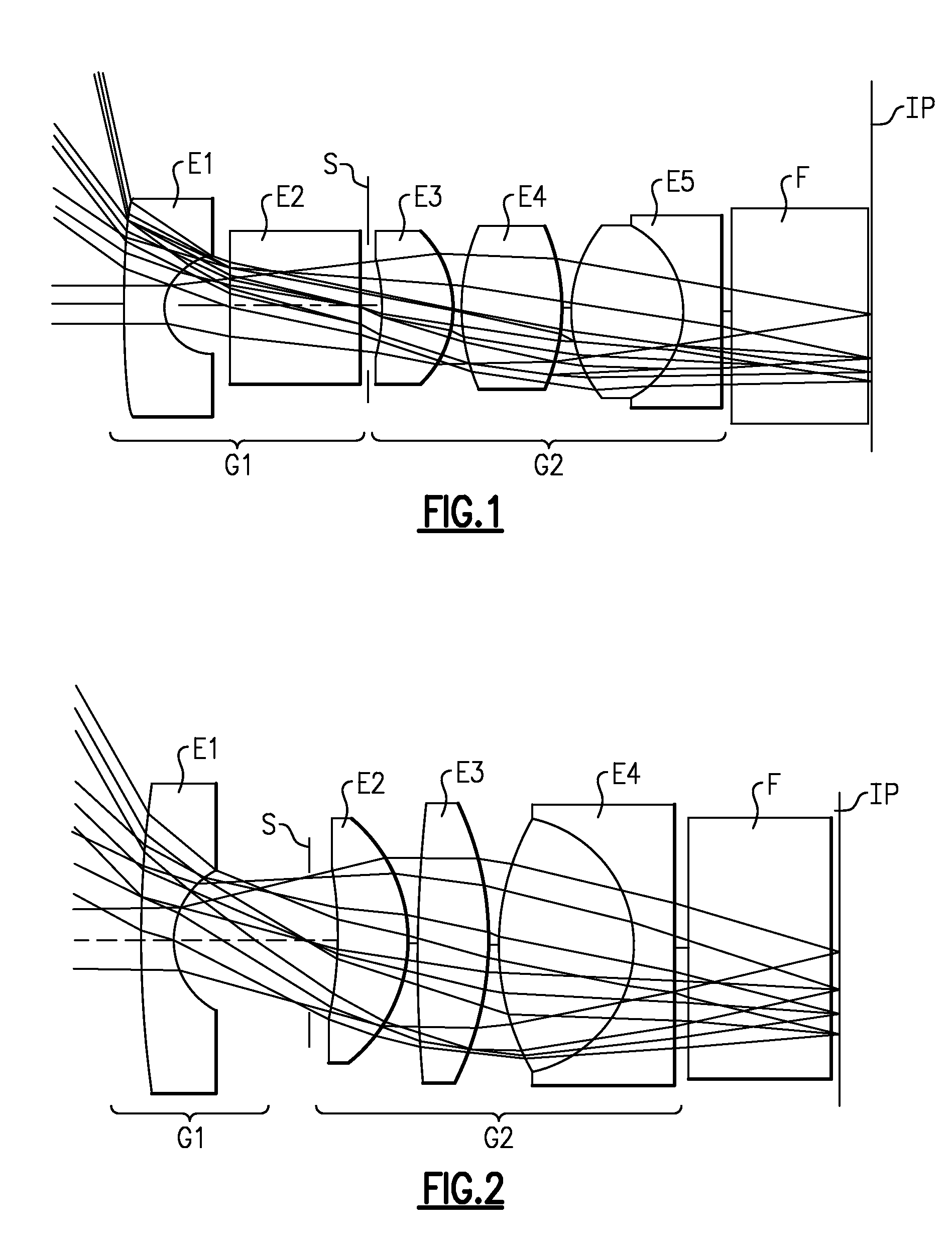
[0041]The schematic constitution of an endoscope objective lens of Example 1 is shown in FIG. 1. In this endoscope objective lens, the negative lens group, G1, arranged proximate the object side comprises a negative lens element E1 directing its concave surface to the image side, and a flat element (zero power element) E2. The positive lens group, G2, arranged distal the object side comprises a positive lens element E3 directing its convex surface to the image side, a positive lens element E4, and a doublet lens element, E5. A stop, S, is placed between the negative lens group, G1, and the positive lens group, G2, and an optical filter, F, is placed between the last lens element E5 of the positive lens group, G2, and the image plane, IP. In one embodiment, the optical filter, F, comprises a laser rejection filter. The doublet lens element, E5, comprises two elements having a refractive index greater than 0.02 and an Abbe number difference greater than 15.0 for correcting chromatic, ...
example 2
[0043]The schematic constitution of an endoscope objective lens of Example 2 is shown in FIG. 2. In this endoscope objective lens, the negative lens group, G1, arranged proximate the object side comprises a negative lens element E1 directing its concave surface to the image side. The positive lens group, G2, arranged distal the object side comprises a positive lens element E2 directing its convex surface to the image side, a positive lens element E3, and a doublet lens element, E4. A stop, S, is placed between the negative lens group, G1, and the positive lens group, G2, and an optical filter, F, is placed between the last lens element E5 of the positive lens group, G2, and the image plane, IP. In one embodiment, the optical filter, F, comprises a laser rejection filter. The doublet lens element, E4, comprises two elements having a refractive index greater than 0.02 and an Abbe number difference greater than 15.0 for correcting chromatic, coma, and spherical aberration in visible an...
example 3
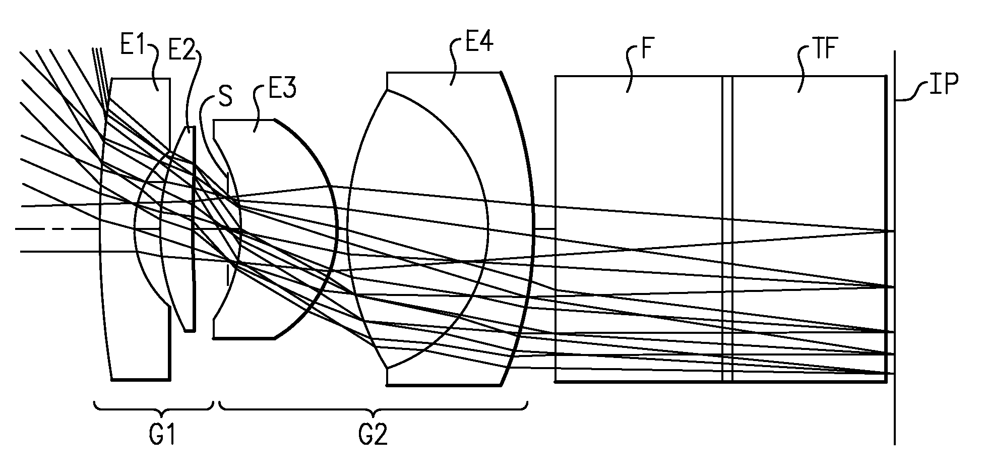
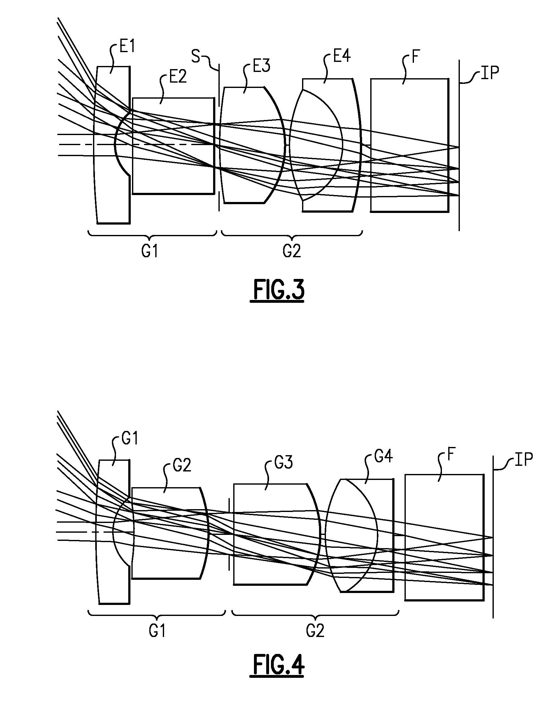
[0045]The schematic constitution of an endoscope objective lens of Example 3 is shown in FIG. 3. In this endoscope objective lens, the negative lens group, G1, arranged proximate the object side comprises a negative lens element E1 directing its concave surface to the image side, and a flat element (zero power element) E2. The positive lens group, G2, arranged distal the object side comprises a positive lens element E3 directing its convex surface to the image side, and a doublet lens element E4. A stop, S, is placed between the negative lens group, G1, and the positive lens group, G2, and an optical filter, F, is placed between the last lens element E5 of the positive lens group, G2, and the image plane, IP. In one embodiment, the optical filter, F, comprises a laser rejection filter.
[0046]Radius of curvature R (mm) of each lens surface, thickness or air gap (mm) between lenses, glass code, and semi-aperture are listed in TABLE III. Note that numbers in the table indicate the order...
PUM
 Abstract
Description
Claims
Application Information